VLAN Trunking Protocol

VTP (VLAN Trunking Protocol) maintains VLAN configuration consistency across the entire network. VTP uses Layer 2 trunk frames to manage the addition, deletion, and renaming of VLANs on a network-wide basis from a centralized switch in the VTP server mode. VTP is responsible for synchronizing VLAN information within a VTP domain and reduces the need to configure the same VLAN information on each switch.
VTP minimizes the possible configuration inconsistencies that arise when changes are made. These inconsistencies can result in security violations, because VLANs can cross connect when duplicate names are used. They also could become internally disconnected when they are mapped from one LAN type to another, for example, Ethernet to ATM LANE ELANs or FDDI 802.10 VLANs. VTP provides a mapping scheme that enables seamless trunking within a network employing mixed-media technologies.
VTP provides the following benefits:
- VLAN configuration consistency across the network
- Mapping scheme that allows a VLAN to be trunked over mixed media
- Accurate tracking and monitoring of VLANs
- Dynamic reporting of added VLANs across the network
- Plug-and-play configuration when adding new VLANs
As beneficial as VTP can be, it does have disadvantages that are normally related to the spanning tree protocol (STP) as a bridging loop propagating throughout the network can occur. Cisco switches run an instance of STP for each VLAN, and since VTP propagates VLANs across the campus LAN, VTP effectively creates more opportunities for a bridging loop to occur.
Before creating VLANs on the switch that will propagate via VTP, a VTP domain must first be set up. A VTP domain for a network is a set of all contiguously trunked switches with the same VTP domain name. All switches in the same management domain share their VLAN information with each other, and a switch can participate in only one VTP management domain. Switches in different domains do not share VTP information.
Using VTP, each Catalyst Family Switch advertises the following on its trunk ports:
- Management domain
- Configuration revision number
- Known VLANs and their specific parameters
Configuring VLAN Trunks
A VLAN trunk physically links two VLAN-capable switches or a VLAN-capable switch and a VLAN-capable router. VLAN trunks carry the traffic of multiple VLANs so you can extend VLANs from one Catalyst series switch to another.
Note ![]() VLANs cannot be connected by bridge groups.
VLANs cannot be connected by bridge groups.
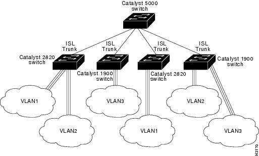
The Enterprise Edition software for Catalyst 2820 or Catalyst 1900 switches supports a maximum of 27 switched ports. On the Catalyst 2820 switch, you can configure only the single-port 100BaseTX or 100BaseFX and ATM modules as trunks. On the Catalyst 1900, you can configure the 100BaseTX or 100Base FX ports as trunks.
The Dynamic Inter-Switch Link Protocol (DISL) protocol synchronizes the configuration of two interconnected Fast Ethernet interfaces into an ISL trunk. The DISL protocol ensures that both of the Fast Ethernet interfaces are either in trunking or nontrunking mode.
If you are using VTP to propagate VLAN information, you must enable a trunk to receive and propagate VLAN information through network advertisements. The switch then learns the management domain and the VLANs within it that are defined on all other switches. ISL-capable switch ports process DISL packets from switches that have the same VTP domain name or a null domain name. If a switch port receives a DISL packet with a different VTP domain name than the domain name configured on the switch, the packet is discarded.
shows an example of a Fast Ethernet ISL configuration.
Figure 2-7 Catalyst 2820 Switches and Catalyst 1900 Switches in a Fast Ethernet ISL Configuration
DISL Port States
The DISL protocol requires that there is a point-to-point ISL connection between two devices. DISL-capable ports can be configured to be in any of the states described in Table 2-3.
Table 2-3
|
Port State
|
Description
|
|---|---|
|
On |
Configures the port in permanent ISL trunk mode and negotiates with the connected device to convert the link to trunk mode. The port converts to a trunk, even if the other end of the link does not. This state is used when an ISL port is connected to another ISL port that does not support the DISL protocol. |
|
Off |
Disables port trunking and negotiates with the connected device to convert the link to nontrunk. The port converts to a nontrunk mode, even if the other end of the link does not. This state is used when an ISL port is connected to another ISL port that does not support the DISL protocol. (Default) |
|
Desirable |
Triggers the port to negotiate the link from nontrunking to trunking mode. The port negotiates to a trunk port if the connected device is either in the On, Desirable, or Auto state. Otherwise, the port becomes a nontrunk port. |
|
Auto |
Enables a port to become a trunk only if the connected device has the state set to On or Desirable. |
|
No-negotiate |
Configures the port in permanent ISL trunk mode, but the port does not generate or process DISL frames. Use this state when an ISL port is connected to another ISL port (such as a router ISL port) that does not support the DISL protocol. |
DISL Port States
The status of a VLAN port is shown in the grayed out field in the Status column of the web console Port Management Page. These non-configurable VLAN states indicate the DISL status of a port and whether or not the port has been disabled or suspended because no VLAN has been configured for the port.
Table 2-4 VLAN Port Status
|
VLAN Port Status
|
Description
|
|---|---|
|
Suspended-DISL |
The port is suspended due to DISL negotiation. |
|
Suspended No-VLAN |
The port is suspended because there is no VLAN assigned to the port. |
|
Disabled No-VLAN |
The port is disabled because the VLAN assigned to the port does not exist. |
Verifying Trunk Configuration
To verify that you have configured the selected port as a trunk port, check the trunking status and encapsulation type at the top of the Trunk Configuration screen. (When a link is present, a Fast Ethernet trunk shows ISL encapsulation. An ATM module shows LANE encapsulation.) From the Main Menu, access the Port Configuration Menu to see the status of each active VLAN.
Adding a VLAN to an Allowed List
Each trunk has a list of VLANs called allowed VLANs that are enabled to receive and transmit all types of traffic on that trunk. You must configure the VLAN and add it to the allowed list for the trunk so that it can receive trunk traffic. By default, all configured VLANs are allowed on a trunk. To add a VLAN to the allowed list, do the following:
|
Step
|
Action
|
|---|---|
|
1 |
Select [V] from the Main Menu. |
|
2 |
Enter [T] Trunk Configuration. |
|
3 |
At the next menu, enter [A] or [B] at the selection prompt, and press Return. |
|
4 |
a. Enter [A] Add Allowed VLANs at the selection prompt. b. Enter the appropriate VLAN number at the selection prompt in the next menu. The Trunk Configuration Menu reappears. |
Traffic will not be forwarded to or from a VLAN that is not included in the VLAN allowed list.
Verifying a VLAN Allowed List Addition
To verify that you have added a VLAN to the allowed list, select [V] List Allowed VLANs from the Trunk Configuration Menu, and examine the contents of the display.
Deleting a VLAN from the Allowed List
To delete a VLAN from the allowed list, do the following:
|
Step
|
Action
|
|---|---|
|
1 |
Select [V] Virtual LAN from the Main Menu. |
|
2 |
Enter [T] Trunk Configuration. |
|
3 |
a. Select [D] Delete Allowed VLAN(s). b. Enter the appropriate VLAN number at the selection prompt in the next menu, and press Return. |
Viewing the List of Allowed VLANs
To view the list of allowed VLANs, select [V] List Allowed VLANs from the Trunk Configuration Menu.
Adding a Pruning-Eligible VLAN
The flood traffic of a VLAN is typically sent to all switches in the same management domain that are connected by trunks. Pruning VLANs restricts the flood traffic of a VLAN to just those switches that have member ports. When you prune eligible VLANs, you restrict the flood traffic of those VLANsTo add a pruning-eligible VLAN, do the following:
|
Step
|
Action
|
|---|---|
|
1 |
Select [V] from the Main Menu. |
|
2 |
Enter [T] Trunk Configuration. |
|
3 |
At the next menu, enter [A] or [B] at the selection prompt, and press Return. |
|
4 |
a. Enter [E] Add Pruning Eligible VLAN(s) at the selection prompt. b. Enter the appropriate VLAN number at the selection prompt in the next menu. The Trunk Configuration Menu reappears. |
Verifying Pruning-Eligible VLAN Additions
To verify that you have added a pruning-eligible VLAN, select [T] Trunk Configuration, and view the contents of the display. To view additional VLAN information, select [F] List Pruning Eligible VLANs.
Deleting a Pruning-Eligible VLAN
To delete a pruning -eligible VLAN, do the following:
|
Step
|
Action
|
|---|---|
|
1 |
Select [V] from the Main Menu. |
|
2 |
Enter [T] Trunk Configuration. |
|
3 |
a. Select [C] Delete Pruning Eligible VLAN(s). b. Enter the appropriate VLAN number at the selection prompt in the next menu, and press Return. |
Viewing a List of Pruning-Eligible VLANs
To view the list of pruning-eligible VLANs, select [F] List Pruning Eligible VLANs from the Trunk Configuration Menu.
For more information about pruning.
Displaying VLANs Transmitting and Receiving Flooded Traffic
You can use the Trunk Configuration Menu to display the following lists:
•![]() A list of VLANs on which flooded traffic is transmitted over a specified trunk
A list of VLANs on which flooded traffic is transmitted over a specified trunk
If a remote switch on a specified trunk requests the local switch to transmit flooded traffic on a specific list of VLANs, you can display that VLAN list on the local switch. At the selection prompt of the Trunk Configuration Menu, select [S] List VLANs that Transmit Flooded Traffic.
•![]() A list of VLANs on which flooded traffic is received over a specified trunk
A list of VLANs on which flooded traffic is received over a specified trunk
If a local switch on a specified trunk requests the remote switch to transmit flooded traffic on a specific list of VLANs, you can display that VLAN list on the local switch. At the selection prompt of the Trunk Configuration Menu, select [R] List VLANs that Receive Flooded Traffic.
VLAN Trunk Protocol
The VTP maintains VLAN configuration consistency throughout the network. VTP manages the addition, deletion, and modification of VLANs at the system level, automatically communicating this information to all the other switches in the network. In addition, VTP minimizes these possible configuration inconsistencies that can result in security violations:
•![]() VLANs can become cross-connected when duplicate names are used.
VLANs can become cross-connected when duplicate names are used.
•![]() VLANs can become internally disconnected when they are incorrectly mapped between one LAN type and the other.
VLANs can become internally disconnected when they are incorrectly mapped between one LAN type and the other.