Virtual LAN Basics

A VLAN is a switched network that is logically segmented by functions, project teams, or applications without regard to the physical location of users. For example, several end stations might be grouped as a department, such as engineering or accounting. When the end stations are physically located close to one another, you can group them into a LAN segment. If any of the end stations are in different buildings (not the same physical LAN segment), you can then group them into a VLAN.
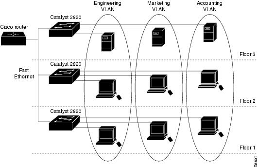
You can assign each switch port to a VLAN. Ports in a VLAN share broadcast traffic. Ports that do not belong to that VLAN do not share the broadcast traffic. Ports from multiple Catalyst 2820 and Catalyst 1900 switches can be members of the same VLAN. shows an example of VLANs that span multiple switches and multiple floors or a building.
Figure 2-1 VLANs Spanning Multiple Switches and Multiple Floors
Features
VLANs provide the following features:
•![]() Simplification of end-station moves, adds, and changes
Simplification of end-station moves, adds, and changes
When an end station is physically moved to a new location, its attributes can be reassigned from a network management station through Simple Network Management Protocol (SNMP) or through the user interface menus. When an end station is moved within the same VLAN, it retains its previously assigned attributes in its new location. When an end station is moved to a different VLAN, the attributes of the new VLAN are applied to the end station.
You can assign the Internet Protocol (IP) address of a Catalyst 2820 or Catalyst 1900 switch to any VLAN. A network management station and workstations on any Catalyst series switch VLAN then have direct access to other Catalyst 2820 and
Catalyst 1900 switches on the same VLAN, without needing a router. Only one IP address can be assigned to a Catalyst 2820 or Catalyst 1900 switch; if the IP address is reassigned to a different VLAN, the previous IP address assignment to a VLAN is invalid.
•![]() Controlled traffic activity
Controlled traffic activity
VLANs allow ports on the same or different switches to be grouped so that traffic is confined to members of only that group. This feature restricts broadcast, unicast, and multicast traffic (flooding) only to ports included in a certain VLAN. The management domain is a group of VLANs that are managed by a single administrative authority. You can create VLANs for an entire management domain from a single Catalyst 2820 or Catalyst 1900 switch.
•![]() Workgroup and network security
Workgroup and network security
You can increase security by segmenting the network into distinct broadcast domains. To this end, VLANs can restrict the number of users in a broadcast domain. You can also control the size and composition of the broadcast domain by controlling the size and composition of a VLAN.
shows the capabilities and defaults for the Catalyst 2820 and Catalyst 1900 VLAN features.
Table 2-1
|
Feature
|
Capability
|
Default
|
|---|---|---|
|
Trunk ports |
Supports a maximum of two trunks. The Catalyst 1900 switch supports a maximum of two Inter-Switch Link (ISL) trunks. The Catalyst 2820 switch supports both ISL and Asynchronous Transfer Mode (ATM) LAN emulation (LANE) trunk connections and ATM permanent virtual connections (PVCs). Fast Ethernet trunk ports can be grouped using the Fast EtherChannel feature to form a single trunk. |
No trunk ports are enabled. |
|
Load sharing |
Supports Spanning-Tree Protocol (STP) on VLAN trunks to load share. |
No load sharing is set up. |
|
VLAN Trunk Protocol (VTP) |
Supports server, client, and transparent modes. However, you can only configure server and transparent modes. Server and transparent modes support a maximum of 128 VLANs. From server mode, the switch automatically transitions to client mode if it learns more than 128 VLANs from advertisements. Client mode supports |
Configured to server mode. Set to no-management domain state. |
|
VTP pruning |
Supports pruning. |
Pruning is disabled. |
|
VLAN membership |
Supports dynamic and static ports. |
The default VLAN membership of all ports is static, and all ports reside in VLAN 1. |
|
VLAN Membership Policy Server (VMPS) |
Does not function as a VMPS on the network. (The Catalyst 5000 series switches support this feature.) |
No default. |
|
STP |
Runs on a maximum of 64 VLANs at one time. |
VLANs 1 to 64 are enabled with STP. |
Components
Networks that have VLANs contain one or more of the following components:
•![]() Switches that logically segment connected end stations
Switches that logically segment connected end stations
Switches are the entry points into the switched fabric for end-station devices and can group users, ports, or logical addresses into common communities of interest.
You can use both a single switch or multiple connected switches to group ports and users into communities. By grouping ports and users together across multiple switches, VLANs can span single-building infrastructures, interconnected buildings, or campus networks.
Switches use frame identification, or tagging, to logically group users into administratively defined VLANs. Based on rules you define, tagging determines where the frame is to be sent by placing a unique identifier in the header of each frame before it is forwarded throughout the switch fabric. The identifier is examined and understood by each switch prior to any broadcasts or transmissions to other switches, routers, or end-station devices. When the frame exits the switch fabric, the switch removes the identifier before the frame is transmitted to the target end station.
You can logically group users on Ethernet and ATM networks by mapping VLANs on the Ethernet network to emulated LANs (ELANs) on the ATM network.
•![]() Routers that provide VLAN communications between workgroups
Routers that provide VLAN communications between workgroups
Routers provide policy-based control, broadcast management, and route processing and distribution. They also provide the communication between VLANs and the access to shared resources, such as servers and hosts. Routers connect to other parts of the network that are either logically segmented into subnets or that require access to remote sites across wide area links. Routers are integrated into the switching fabric by using high-speed backbone connections over Fast Ethernet, FDDI, or ATM for higher throughput between switches and routers.
•![]() Transport protocols that carry VLAN traffic across shared LAN and ATM backbones
Transport protocols that carry VLAN traffic across shared LAN and ATM backbones
The VLAN transport protocol enables information to be exchanged between interconnected switches residing on the corporate backbone.
The backbone acts as the aggregation point for high-volume traffic. It also carries end-user VLAN information and identification between switches, routers, and directly attached servers. Within the backbone, high-bandwidth, high-capacity links carry the traffic throughout the enterprise.
•![]() Interoperability with previously installed LAN systems
Interoperability with previously installed LAN systems
VLANs provide compatibility with previously installed systems, such as shared hubs and stackable devices. You can add shared hubs without changing existing network equipment. You also can share traffic and network resources that attach directly
to switching ports with VLAN designations.