WAN Cabling Standards

Understanding WAN Cabling
Just as several types of physical layer implementations for LANs exist, various kinds of serial and router connections can also be used in a WAN environment, depending on the network requirements.
Learning about the different types of WAN serial and router connections and their functions can help you understand more about how a WAN works.
WAN Physical Layer
Many physical implementations carry traffic across the WAN. Needs vary, depending on the distance of the equipment from the services, the speed, and the actual service itself. Figure 4-15 shows a subset of physical implementations that support some of the more prominent WAN solutions today.
 Figure 4-15 WAN at the Physical Layer
Serial connections support WAN services such as dedicated leased lines that run the Point-to-Point Protocol (PPP) or Frame Relay. The speed of these connections ranges up to E1 (2.048 Mbps).
Other WAN services, such as ISDN, offer dial-on-demand connections or dial backup services. An ISDN BRI is composed of two 64-kbps bearer channels (B channels) for data, and one 16-kbps data channel (D channel) for signaling and other link-management tasks. PPP is typically used to carry data over the B channels.
With the increasing demand for residential broadband high-speed services, DSL and cable modem connections are beginning to dominate. For example, typical residential DSL service can offer a speed of up to 1.5 Mbps over the existing telephone line. Cable services, which work over the existing coaxial cable TV line, also offer high-speed connectivity matching or surpassing that of DSL.
WAN Serial Connections
For long-distance communication, WANs use serial transmission. Serial transmission is a method of data transmission in which bits of data are transmitted sequentially over a single channel. This one-at-a-time transmission contrasts with parallel data transmission, which transmits several bits at a time. To carry the bits, serial channels use a specific electro-magnetic or optical frequency range.
Figure 4-16 shows all the different serial connector options available for Cisco routers.
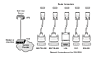 Figure 4-16 Serial Connectors
Serial ports on Cisco routers use a proprietary 60-pin connector or smaller "smart serial" connector. The type of connector on the other end of the cable is dependent on the service provider or end-device requirements.
Frequencies, described in terms of their cycles per second (Hz), function as a band or spectrum for communication. For example, the signals transmitted over voice-grade telephone lines use up to 3 kHz. The size of this frequency range is called the bandwidth. Another way to express bandwidth is to specify the amount of data in bits per second that can be carried using two of the physical layer implementations (EIA/TIA-232 and EIA/TIA-449). Table 4-4 compares physical standards for these two WAN serial connection options.
Table 4-3 Comparison of Physical Serial Standards
|
Data Rates in bps |
EIA/TIA-232 Distance in Meters |
EIA/TIA-449 Distance in Meters |
|
2400 |
60 |
1250 |
|
4800 |
30 |
625 |
|
9600 |
15 |
312 |
|
19,200 |
15 |
156 |
|
38,400 |
15 |
78 |
|
115,200 |
3.7 |
N/A |
|
1,544,000 (T1) |
N/A |
15 |
Several types of physical connections allow you to connect to serial WAN services. Depending on the physical implementation that you choose or the physical implementation that your service provider imposes, you need to select the correct serial cable type to use with the router.
Serial Connections
In addition to determining the cable type, you need to determine whether you need data terminal equipment (DTE) or data circuit-terminating equipment (DCE) connectors for your WAN equipment. The DTE is the endpoint of the user's device on the WAN link. The DCE is typically the point where responsibility for delivering data passes into the hands of the service provider.
As shown in Figure 4-17, if you are connecting directly to a service provider, or to a device (like a channel/data service unit [CSU/DSU]) that performs signal clocking, the router is a DTE and needs a DTE serial cable. This situation is typically the case for routers.
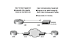 Figure 4-17 DTE and DCE Connections
In some cases, the router needs to be the DCE. For example, if you are performing a back-to-back router scenario in a test environment, one of the routers is a DTE, and the other is a DCE. Figure 4-18 shows a back-to-back router configuration. To implement this, you need a DTE cable for one router, and a DCE cable for another router. You might also be able to buy a special back-to-back cable, which is wired with a DTE side and DCE side.
 Figure 4-18 Back-to-Back Router Connections
When you are cabling routers for serial connectivity, the routers have either fixed or modular ports. The type of port being used affects the syntax that you use later to configure each interface.
Figure 4-19 shows an example of a router with fixed serial ports (interfaces). Each port is given a label of port type and port number, for example, Serial 0. To configure a fixed interface, specify the interface using this convention.
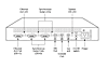 Figure 4-19 Fixed Serial Ports
Figure 4-20 shows examples of routers with modular serial ports. Usually, each port is given a label of port type, slot (the location of the module), and port number. To configure a port on a modular card, it is necessary to specify the interface using the convention "port type slot number/port number." For example, given serial 1/0, the type of interface is a serial interface, the slot number where the interface module is installed is slot 1, and the port referenced on that serial interface module is port 0.
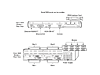 Figure 4-20 Modular Serial Portsts
ISDN BRI Connections
With ISDN BRI, you can use two types of interfaces: BRI S/T and BRI U, which are reference points for user connectivity. To determine the appropriate interface, you need to verify whether you or the service provider provides a Network Termination 1 (NT1) device.
An NT1 device is an intermediate device between the router and the service provider ISDN switch (cloud) that connects four-wire subscriber wiring to the conventional two-wire local loop. In North America, the customer typically provides the NT1, while in the rest of the world, the service provider provides the NT1 device.
You might find it necessary to provide an external NT1 if an NT1 is not integrated into the router. Looking at the labeling on the router interface is the easiest way to determine if the router has an integrated NT1. A BRI interface with an integrated NT1 is labeled BRI U, and a BRI interface without an integrated NT1 is labeled BRI S/T. Because routers can have multiple ISDN interface types, you must determine the interface needed when the router is purchased. You can determine the type of ISDN connector that the router has by looking at the port label.
Figure 4-21 shows the different port types for the ISDN interface. To interconnect the ISDN BRI port to the service-provider device, use a UTP Category 5 straight-through cable.
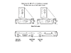 Figure 4-21 ISDN Interface Types
WARNING
It is important to insert a cable running from an ISDN BRI port only to an ISDN jack or an ISDN switch. ISDN BRI uses voltages that can seriously damage non-ISDN devices.
DSL Connections
Routers can also be connected to an asymmetric digital subscriber line (ADSL). The Cisco 827 ADSL router has one ADSL interface. To connect an ADSL to the ADSL port on a router, one end of the phone cable is connected to the ADSL port on the router. The other end of the phone cable is connected to the external wall phone jack.
To connect a router for DSL service, you need a phone cable with RJ-11 connectors. The RJ-11 connector is the same one used on a traditional telephone connection and is slightly smaller than a RJ-45 connector. Figure 4-22 shows a connection to a phone jack with DSL services. DSL works over standard telephone lines. It uses only two pins on the RJ-11 connector.
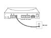 Figure 4-22 DSL Connection
Cable Connections
The Cisco uBR905 cable access router provides high-speed network access on the cable television system to residential and small office/home office (SOHO) subscribers. The uBR905 router has an F-connector coaxial cable interface that can be connected to a cable system.
To connect the Cisco uBR905 cable access router to the cable system, a cable splitter/directional coupler can be installed, if needed, to separate signals for TV and computer use. If necessary, you can also install a high-pass filter to prevent interference between TV and computer signals.
The coaxial cable is connected to the F connector of the router, as shown in Figure 4-23.
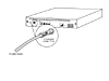 Figure 4-23 Cable Connection
Asynchronous Router Connections
All Cisco devices also have at least one asynchronous connection that is used for management purposes. In some cases, these devices might also have an auxiliary asynchronous device that can be used for management or dialup network connections. When configuring and managing Cisco devices, you must be aware of how to connect to these ports.
Console Port Connections
To initially configure the Cisco device, you must provide a management connection, also known as a console connection, directly to the device. For Cisco equipment, this manage-ment attachment is called a console port. The console port allows monitoring and configuring of a Cisco hub, switch, or router.
The cable used between a terminal and a console port is a rollover cable, with RJ-45 connectors as illustrated in Figure 4-24.
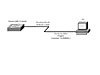 Figure 4-24 Connecting a Device with a Console Cable
The rollover cable, also known as a console cable, has a different pinout than the straight-through or crossover RJ-45 cables used with Ethernet or the ISDN BRI. The pinout for a rollover cable is as follows:
1–8
2–7
3–6
4–5
5–4
6–3
7–2
8–1
To set up the connection between your terminal and the Cisco console port, you must perform the following:
|
Step 1 |
Cable the device to the PC using a rollover cable. You might need an RJ-45- to-DB-9 or and RJ-45-to-DB25 adapter for your PC or terminal. |
|
Step 2 |
Configure terminal emulation software for the PC with the following COM port settings: 9600 bps, 8 data bits, no parity, 1 stop bit, and no flow control. |
This connection to the console port provides you with access to the device's executive process command-line interface (CLI). From there, you can configure the device.
NOTE
Many PCs and laptops are no longer manufactured with a 25- or 9-pin (legacy) serial connector. Instead, most devices now ship with USB connectors. If you are working with a USB connector, you need to obtain a USB-to-DB-9 converter cable to connect to the console.
Auxiliary Connections
The auxiliary (AUX) port is another asynchronous connection that can provide out-of-band management—management not using the network bandwidth—through a modem. To provide out-of-band management, you can connect a modem directly to the AUX port. When you dial the modem, you are connected to the AUX port and the executive process CLI. The AUX port must be configured using the console port before it can be used in this manner.
The AUX port can also be used as a dial-on-demand WAN port for passing user traffic.