Spanning Tree Working and Convergence

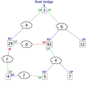
The collection of bridges in a local area network (LAN) can be depicted as a graph whose nodes are bridges and LAN segments (or cables), and whose edges are the interfaces connecting the bridges to the segments. To break loops in the LAN while maintaining access to all LAN segments, the bridges collectively compute a spanning tree. The spanning tree is not necessarily a minimum cost spanning tree. A network administrator can reduce the cost of a spanning tree, if necessary, by altering some of the configuration parameters in such a way as to affect the choice of the root of the spanning tree. The spanning tree that the bridges compute using the Spanning Tree Protocol can be determined using the following rules. The example network at the right, below, will be used to illustrate the rules.


Select a root bridge. The root bridge of the spanning tree is the bridge with the smallest (lowest) bridge ID. Each bridge has a configurable priority number and a MAC Address; the bridge ID contains both numbers combined together - Bridge priority + MAC (32768.0200.0000.1111). The Bridge priority default is 32768 and can only be configured in multiples of 4096. To compare two bridge IDs, the priority is compared first, as if looking at a real number anything less than 32768...will become the target of being the root. If two bridges have equal priority then the MAC addresses are compared; for example, if switches A (MAC=0200.0000.1111) and B (MAC=0200.0000.2222) both have a priority of 32768 then switch A will be selected as the root bridge. If the network administrators would like switch B to become the root bridge, they must set its priority to be less than 32768 or configure the spanning tree a root primary/secondary. When configuring the root primary and root secondary the switch will automatically change the priority accordingly, 24577 and 28673 respectively with the default configuration.
Determine the least cost paths to the root bridge. The computed spanning tree has the property that messages from any connected device to the root bridge traverse a least cost path, i.e., a path from the device to the root that has minimum cost among all paths from the device to the root. The cost of traversing a path is the sum of the costs of the segments on the path. Different technologies have different default costs for network segments. An administrator can configure the cost of traversing a particular network segment. The property that messages always traverse least-cost paths to the root is guaranteed by the following two rules.
Least cost path from each bridge. After the root bridge has been chosen, each bridge determines the cost of each possible path from itself to the root. From these, it picks one with the smallest cost (a least-cost path). The port connecting to that path becomes the root port (RP) of the bridge.
Least cost path from each network segment. The bridges on a network segment collectively determine which bridge has the least-cost path from the network segment to the root. The port connecting this bridge to the network segment is then the designated port (DP) for the segment.
Disable all other root paths. Any active port that is not a root port or a designated port is a blocked port (BP).
Modifications in case of ties. The above rules over-simplify the situation slightly, because it is possible that there are ties, for example, two or more ports on a single bridge are attached to least-cost paths to the root or two or more bridges on the same network segment have equal least-cost paths to the root. To break such ties:
Breaking ties for root ports. When multiple paths from a bridge are least-cost paths, the chosen path uses the neighbor bridge with the lower bridge ID. The root port is thus the one connecting to the bridge with the lowest bridge ID. For example, in figure 3, if switch 4 was connected to network segment d instead of segment c, there would be two paths of length 2 to the root, one path going through bridge 24 and the other through bridge 92. Because there are two least cost paths, the lower bridge ID (24) would be used as the tie-breaker in choosing which path to use.
Breaking ties for designated ports. When more than one bridge on a segment leads to a least-cost path to the root, the bridge with the lower bridge ID is used to forward messages to the root. The port attaching that bridge to the network segment is the designated port for the segment. In figure 4, there are two least cost paths from network segment d to the root, one going through bridge 24 and the other through bridge 92. The lower bridge ID is 24, so the tie breaker dictates that the designated port is the port through which network segment d is connected to bridge 24. If bridge IDs were equal, then the bridge with the lowest MAC address would have the designated port. In either case, the loser sets the port as being blocked.
The final tie-breaker. In some cases, there may still be a tie, as when two bridges are connected by multiple cables. In this case, multiple ports on a single bridge are candidates for root port. In this case, the path which passes through the port on the neighbor bridge that has the lowest port identifier [Port priority(default=128) + Port number] is used.
In summary, the sequence of events to determine the best received BPDU (which is your best path to the root) is
- lowest root bridge id
- lowest root path cost
- lowest sender bridge id
- lowest sender port id
Election of the Root Switch
All switches in an extended LAN participating in Spanning-Tree Protocol gather information on other switches in the network through an exchange of data messages. These messages are bridge protocol data units (BPDUs). This exchange of messages results in the following:
- The election of a unique root switch for the stable spanning-tree network topology.
- The election of a designated switch for every switched LAN segment.
- The removal of loops in the switched network by placing redundant switch ports in a backup state.
The Spanning-Tree Protocol root switch is the logical center of the spanning-tree topology in a switched network. All paths that are not needed to reach the root switch from anywhere in the switched network are placed in Spanning-Tree Protocol backup mode. Table C-1 describes the root switch variables, that affect the entire spanning-tree performance.
Table C-1: Root Switch Variables Affecting STP
Figure C-1 shows how BPDUs enable a Spanning-Tree Protocol topology.
Figure C-1: BPDUs Enabling a Stable Spanning-Tree Protocol Topology

Bridge Protocol Data Units
The stable active topology of a switched network is determined by the following:
- The unique switch identifier (MAC address) associated with each switch.
- The path cost to the root associated with each switch port.
- The port identifier (MAC address) associated with each switch port.
Each configuration BPDU contains the following minimal information:
- The unique identifier of the switch that the transmitting switch believes to be the root switch.
- The cost of the path to the root from the transmitting port.
- The identifier of the transmitting port.
The switch sends configuration BPDUs to communicate and compute the spanning-tree topology. A MAC frame conveying a BPDU sends the switch group address to the destination address field. All switches connected to the LAN on which the frame is transmitted receive the BPDU. BPDUs are not directly forwarded by the switch, but the information contained in the frame can be used to calculate a BPDU by the receiving switch, and, if the topology changes, instigate a BPDU transmission.
A BPDU exchange results in the following:
- One switch is elected as the root switch.
- The shortest distance to the root switch is calculated for each switch.
- A designated switch is selected. This is the switch closest to the root switch through which frames will be forwarded to the root.
- A port for each switch is selected. This is the port providing the best path from the switch to the root switch.
- Ports included in the Spanning-Tree Protocol are selected.
Spanning-Tree Protocol Configuration
If all switches are enabled with default settings, the switch with the lowest MAC address in the network becomes the root switch. The network in Figure C-2 assumes that Switch A has the lowest MAC address and is therefore the root switch. However, due to traffic patterns, number of forwarding ports, or line types, Switch A might not be the ideal root switch. By increasing the priority (lowering the numerical priority number) of the ideal switch so that it then becomes the root switch, you force a Spanning-Tree Protocol recalculation to form a new, stable topology.
Figure C-2: Configuring a Stable Topology

For example, assume that Port 2 on Switch B in Figure C-3 is a fiber-optic link, and that Port 1 on Switch B (a UTP link) is the root port. Network traffic might be more efficiently handled over the high-speed fiber-optic link. By changing the Port Priority parameter for Port 2 to a higher priority (lower numerical value) than Port 1, Port 2 becomes the root port. The same change can occur by changing the Port Cost parameter for Port 2 to a lower value than that of Port 1.
Figure C-3: Default Parameters Resulting in Lower Network Efficiency

Spanning-Tree Protocol Port States
Propagation delays can occur when protocol information is passed through a switched LAN. As a result, topology changes can take place at different times and at different places in a switched network. When a switch port transitions directly from non-participation in the stable topology to the forwarding state, it can create temporary data loops. Ports must wait for new topology information to propagate through the switched LAN before starting to forward frames. They must also allow the frame lifetime to expire for frames that have been forwarded using the old topology.
Each port on a switch using Spanning-Tree Protocol exists in one of the following five states:
- Blocking
- Listening
- Learning
- Forwarding
- Disabled
A port moves through these five states as follows:
- From initialization to blocking
- From blocking to listening or to disabled
- From listening to learning or to disabled
- From learning to forwarding or to disabled
- From forwarding to disabled
Figure C-4 illustrates how a port moves through the five states.
Figure C-4: Spanning-Tree Protocol Port States

- The port is put into the listening state while it waits for protocol information that suggests it should go to the blocking state.
- The port waits for the expiration of a protocol timer that moves the port to the learning state.
- In the learning state, the port continues to block frame forwarding as it learns station location information for the forwarding database.
- The expiration of a protocol timer moves the port to the forwarding state, where both learning and forwarding are enabled.
Blocking State
A port in the blocking state does not participate in frame forwarding, as shown in Figure C-5. After initialization, a BPDU is sent to each port in the switch. A switch initially assumes it is the root until it exchanges BPDUs with other switches. This exchange establishes which switch in the network is really the root. If only one switch resides in the network, no exchange occurs, the forward delay timer expires, and the ports move to the listening state. A switch always enters the blocking state following switch initialization.
Figure C-5: Port States

A port in the blocking state performs as follows:
- Discards frames received from the attached segment.
- Discards frames switched from another port for forwarding.
- Does not incorporate station location into its address database. (There is no learning at this point, so there is no address database update.)
- Receives BPDUs and directs them to the system module.
- Does not transmit BPDUs received from the system module.
- Receives and responds to network management messages.
Listening State
The listening state is the first transitional state a port enters after the blocking state, when Spanning-Tree Protocol determines that the port should participate in frame forwarding. Learning is disabled in the listening state. Figure C-5 shows a port in the listening state.
A port in the listening state performs as follows:
- Discards frames received from the attached segment.
- Discards frames switched from another port for forwarding.
- Does not incorporate station location into its address database. (There is no learning at this point, so there is no address database update.)
- Receives BPDUs and directs them to the system module.
- Processes BPDUs received from the system module.
- Receives and responds to network management messages.
Learning State
A port in the learning state is preparing to participate in frame forwarding. This is the second transitional state through which a port moves in anticipation of frame forwarding. The port enters the learning state from the listening state through the operation of Spanning-Tree Protocol.
A port in the learning state performs as follows:
- Discards frames received from the attached segment.
- Discards frames switched from another port for forwarding.
- Incorporates station location into its address database.
- Receives BPDUs and directs them to the system module.
- Receives, processes, and transmits BPDUs received from the system module.
- Receives and responds to network management messages.
Forwarding State
A port in the forwarding state forwards frames, as shown in Figure C-5. The port enters the forwarding state from the learning state through the operation of Spanning-Tree Protocol.
A port in the forwarding state performs as follows:
- Forwards frames received from the attached segment.
- Forwards frames switched from another port for forwarding.
- Incorporates station location information into its address database.
- Receives BPDUs and directs them to the system module.
- Processes BPDUs received from the system module.
- Receives and responds to network management messages.
| Caution Use the immediate-forwarding (portfast) mode only on ports connected to individual workstations to allow these ports to come up and go directly to the forwarding state, rather than having to go through the entire spanning-tree initialization process. To prevent illegal topologies, enable Spanning-Tree Protocol on ports connected to switches or other devices that forward messages. |
Disabled State
A port in the disabled state does not participate in frame forwarding or the operation of Spanning-Tree Protocol, as shown in Figure C-6. A port in the disabled state is virtually nonoperational.
Figure C-6: Port 2 in Disabled State

A disabled port performs as follows:
- Discards frames received from the attached segment.
- Discards frames switched from another port for forwarding.
- Does not incorporate station location into its address database. (There is no learning, so there is no address database update.)
- Receives BPDUs, but does not direct them to the system module.
- Does not receive BPDUs for transmission from the system module.
- Receives and responds to network management messages.