Switches and LED Switch Status

LEDs
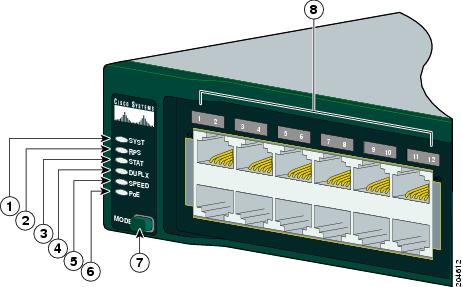
You can use the switch LEDs to monitor switch activity and its performance. Figure 1-23 shows the switch LEDs and the Mode button that you use to select one of the port modes.
All LEDs are visible through the GUI management applications—Network Assistant for multiple switches and the device manager for a single switch. The switch software configuration guide describes how to use the CLI to configure and to monitor individual switches and switch clusters.
Only the Catalyst 2960 PoE switches have a PoE LED.
The four Catalyst 2960 8-port switches and these models do not have an RPS connector or an RPS LED: Catalyst 2960-24-S, Catalyst 2960-24TC-S, Catalyst 2960-48TT-S, Catalyst 2960-48TC-S.
Figure 1-23 Catalyst 2960 Switch LEDs
|
1
|
SYST LED |
5
|
Speed LED |
|
2
|
RPS LED |
6
|
PoE LED1 |
|
3
|
Status LED |
7
|
Mode button |
|
4
|
Duplex LED |
8
|
Port LEDs |
|
1 The PoE LED is only on the Catalyst 2960 PoE switches. |
System LED
The System LED shows whether the system is receiving power and is functioning properly. Table 1-2 lists the LED colors and their meanings.
Table 1-2 System LED
|
Color
|
System Status
|
|---|---|
|
Off |
System is not powered on. |
|
Green |
System is operating normally. |
|
Amber |
System is receiving power but is not functioning properly. |
RPS LED
The RPS LED shows the RPS status. Table 1-3 lists the LED colors and their meanings.
Note The Catalyst 2960 8-port switches, and the Catalyst 2960-24-S, 2960-24TC-S, 2960-48TC-S, and 2960-48TT-S switches do not have an RPS LED.
Table 1-3 RPS LED
|
Color
|
RPS Status
|
|---|---|
|
Off |
RPS is off or not properly connected. |
|
Green |
RPS is connected and ready to provide back-up power, if required. |
|
Blinking green |
RPS is connected but is unavailable because it is providing power to another device (redundancy has been allocated to a neighboring device). |
|
Amber |
The RPS is in standby mode or in a fault condition. Press the Standby/Active button on the RPS, and the LED should turn green. If it does not, the RPS fan could have failed. Contact Cisco Systems. |
|
Blinking amber |
The internal power supply in a switch has failed, and the RPS is providing power to the switch (redundancy has been allocated to this device). |
For more information about the Cisco RPS 2300 or the Cisco RPS 675, see the related hardware installation guide for that power system.
Port LEDs and Modes
The port LEDs, as a group or individually, display information about the switch and about the individual ports (Table 1-4):
Table 1-4 Modes for Port LEDs
|
Selected Mode LED
|
Port Mode
|
Description
|
|---|---|---|
|
STAT |
Port status |
The port status. This is the default mode. |
|
DUPLX |
Port duplex mode |
The port duplex mode: full duplex or half duplex. |
|
SPEED1 |
Port speed |
The port operating speed: 10, 100, or 1000 Mb/s. |
|
PoE2 |
PoE port power |
The PoE status. |
|
1 When installed in Catalyst 2960 switches, 1000BASE-T SFP modules can operate at 10, 100, or 1000 Mb/s in full-duplex mode or at 10 or 100 Mb/s in half-duplex mode. 2 The PoE LED is only on the Catalyst 2960 PoE switches. |
Even if the PoE mode is not selected, the PoE LED shows PoE problems when they are detected (Table 1-5). The PoE LED applies only to Catalyst 2960 switches that support PoE.
Table 1-5 PoE Mode LED
|
Color
|
PoE Status
|
|---|---|
|
Off |
PoE mode is not selected. None of the 10/100 PoE ports have been denied power or are in a fault condition. |
|
Green |
PoE mode is selected, and the PoE status is shown on the port LEDs. |
|
Blinking amber |
PoE mode is not selected. At least one of the 10/100 PoE ports has been denied power, or at least one of the ports has a PoE fault. |
To select or change a mode, press the Mode button until the desired mode is highlighted. When you change port modes, the meanings of the port LED colors also change. Table 1-6 explains how to interpret the port LED colors in different port modes.
Table 1-6 Meaning of Port LED Colors in Different Modes on the Switch
|
Port Mode
|
LED Color
|
Meaning
|
|---|---|---|
|
STAT |
Off |
No link, or port was administratively shut down. |
|
Green |
Link present. |
|
|
Blinking green |
Activity. Port is sending or receiving data. |
|
|
Alternating green-amber |
Link fault. Error frames can affect connectivity, and errors such as excessive collisions, cyclic redundancy check (CRC) errors, and alignment and jabber errors are monitored for a link-fault indication. |
|
|
Amber |
Port is blocked by Spanning Tree Protocol (STP) and is not forwarding data. Note |
|
|
Blinking amber |
Port is blocked by STP and is not sending or receiving packets. |
|
|
DUPLX |
Off |
Port is operating in half duplex. |
|
Green |
Port is operating in full duplex. |
|
|
SPEED |
10/100 and 10/100/1000 ports
|
|
|
Off |
Port is operating at 10 Mb/s. |
|
|
Green |
Port is operating at 100 Mb/s. |
|
|
Blinking green |
Port is operating at 1000 Mb/s. |
|
|
SFP ports
|
||
|
Off |
Port is operating at 10 Mb/s. |
|
|
Green |
Port is operating at 100 Mb/s. |
|
|
Blinking green |
Port is operating at 1000 Mb/s. Note |
|
|
PoE |
Off |
PoE is off. |
|
Green |
PoE is on. The port LED is green only when the switch port is providing power. |
|
|
Alternating green and amber |
PoE is denied because providing power to the powered device will exceed the switch power capacity. The Catalyst 2960-24PC-L, 2960 48PST-L, 2960-48PST-S, and 2960-24PC-S switches provide up to 370 W of power. The Catalyst 2960-24LT-L and 2960-24LC-S switches provide up to 124 W of power. |
|
|
Blinking amber |
PoE is off due to a fault. Caution |
|
|
Amber |
PoE for the port has been disabled. By default, PoE is enabled. |
|
Dual-Purpose Port LEDs
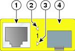
The LEDs on a dual-purpose port show whether an RJ-45 connector is connected to the port, or if an SFP module is installed in the slot. See the example in Figure 1-24. You can configure each port as either a 10/100/1000 port through the RJ-45 connector or as an SFP module, but not both at the same time. The LEDs show how the port is being used (Ethernet or SFP module).
The LED colors have the same meanings as described in Table 1-4 and Table 1-6.
Figure 1-24 Dual-Purpose Port LEDs
|
1
|
RJ-45 connector |
3
|
SFP module port in-use LED |
|
2
|
RJ-45 port in-use LED |
4
|
SFP module slot |
Rear Panel Description
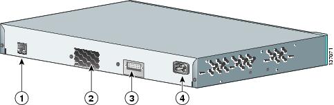
Depending on the Catalyst 2960 switch model, the switch can have an RJ-45 console port, a fan exhaust, an RPS connector, and an AC power connector (see Figure 1-25 for an example of a Catalyst 2960 rear panel).
Figure 1-25 Catalyst 2960 Switch Rear Panel
|
1
|
RJ-45 console port1 |
3
|
RPS connector 2 |
|
2
|
Fan exhaust3 |
4
|
AC power connector4 |
|
1 The Catalyst 2960 8-port switches have the console port on the front panel rather than on the rear panel. 2 These Catalyst 2960 switches do not have an RPS connector: Catalyst 8-port switches, 2960-24-S, 2960-24TC-S, 2960-48TC-S, and 2960-48TT-S switches. 3 The Catalyst 2960 8-port switches do not have a fan. 4 The Catalyst 2960PD-8TT-L switch does not have an AC internal power supply. |