IP Address and Interfaces Configuring
Â

 A basic and required task for configuring IP is to assign IP addresses to network interfaces. Doing so enables the interfaces and allows communication with hosts on those interfaces using IP. Associated with this task are decisions about subnetting and masking the IP addresses.
To configure various IP addressing features, perform the tasks described in the following sections. The task in the first section is required; the tasks in remaining sections are optional.
•Assigning IP Addresses to Network Interfaces (Required)
•Configuring Address Resolution Methods (Optional)
•Enabling IP Routing (Optional)
•Enabling IP Bridging (Optional)
•Enabling Integrated Routing and Bridging (Optional)
•Configuring a Routing Process (Optional)
•Configuring Broadcast Packet Handling (Optional)
•Configuring Network Address Translation (Optional)
•Monitoring and Maintaining IP Addressing (Optional)
Assigning IP Addresses to Network Interfaces
An IP address identifies a location to which IP datagrams can be sent. Some IP addresses are reserved for special uses and cannot be used for host, subnet, or network addresses. Table below lists ranges of IP addresses, and shows which addresses are reserved and which are available for use.
Table Reserved and Available IP Addresses
|
Class
|
Address or Range
|
Status
|
|---|---|---|
|
A |
0.0.0.0 |
Reserved |
|
B |
128.0.0.0 to 191.254.0.0 |
Available |
|
C |
192.0.0.0 |
Reserved |
|
D |
224.0.0.0 to 239.255.255.255 |
Multicast group addresses |
|
E |
240.0.0.0 to 255.255.255.254 |
Reserved |
Â
The official description of IP addresses is found in RFC 1166, Internet Numbers.
To receive an assigned network number, contact your Internet service provider (ISP).
An interface can have one primary IP address. To assign a primary IP address and a network mask to a network interface, use the following command in interface configuration mode:
|
Command
|
Purpose
|
|---|---|
|
Router(config-if)#Â ip address ip-address mask |
Sets a primary IP address for an interface. |
Assigning Multiple IP Addresses to Network Interfaces
Cisco IOS software supports multiple IP addresses per interface. You can specify an unlimited number of secondary addresses. Secondary IP addresses can be used in a variety of situations. The following are the most common applications:
•There might not be enough host addresses for a particular network segment. For example, suppose your subnetting allows up to 254 hosts per logical subnet, but on one physical subnet you must have 300 host addresses. Using secondary IP addresses on the routers or access servers allows you to have two logical subnets using one physical subnet.
•Many older networks were built using Level 2 bridges, and were not subnetted. The judicious use of secondary addresses can aid in the transition to a subnetted, router-based network. Routers on an older, bridged segment can easily be made aware that many subnets are on that segment.
•Two subnets of a single network might otherwise be separated by another network. You can create a single network from subnets that are physically separated by another network by using a secondary address. In these instances, the first network is extended, or layered on top of the second network. Note that a subnet cannot appear on more than one active interface of the router at a time.
To assign multiple IP addresses to network interfaces, use the following command in interface configuration mode:
|
Command
|
Purpose
|
|---|---|
|
Router(config-if)#Â ip address ip-address mask secondary |
Assigns multiple IP addresses to network interfaces. |
A mask identifies the bits that denote the network number in an IP address. When you use the mask to subnet a network, the mask is then referred to as a subnet mask.
Enabling Use of Subnet Zero
Subnetting with a subnet address of 0 is illegal and strongly discouraged (as stated in RFC 791) because of the confusion that can arise between a network and a subnet that have the same addresses. For example, if network 131.108.0.0 is subnetted as 255.255.255.0, subnet 0 would be written as 131.108.0.0—which is identical to the network address.
You can use the all 0s and all 1s subnet (131.108.255.0), even though it is discouraged. Configuring interfaces for the all 1s subnet is explicitly allowed. However, if you need the entire subnet space for your IP address, use the following command in global configuration mode to enable subnet 0:
|
Command
|
Purpose
|
|---|---|
|
Router(config)#Â ip subnet-zero |
Enables the use of subnet zero for interface addresses and routing updates. |
Enabling IP Processing on a Serial Interface
You might want to enable IP processing on a serial or tunnel interface without assigning an explicit IP address to the interface. Whenever the unnumbered interface generates a packet (for example, for a routing update), it uses the address of the interface you specified as the source address of the IP packet. It also uses the specified interface address in determining which routing processes are sending updates over the unnumbered interface. Restrictions are as follows:
•Serial interfaces using High-Level Data Link Control (HDLC), PPP, Link Access Procedure, Balanced (LAPB), and Frame Relay encapsulations, as well as Serial Line Internet Protocol (SLIP) tunnel interfaces, can be unnumbered. Serial interfaces using Frame Relay encapsulation can also be unnumbered, but the interface must be a point-to-point subinterface. It is not possible to use the unnumbered interface feature with X.25 or Switched Multimegabit Data Service (SMDS) encapsulations.
•You cannot use the ping EXEC command to determine whether the interface is up, because the interface has no IP address. The Simple Network Management Protocol (SNMP) can be used to remotely monitor interface status.
•You cannot netboot a runnable image over an unnumbered serial interface.
•You cannot support IP security options on an unnumbered interface.
To enable IP processing on an unnumbered serial interface, use the following command in interface configuration mode:
|
Command
|
Purpose
|
|---|---|
|
Router(config-if)#Â ip unnumbered type number |
Enables IP processing on a serial or tunnel interface without assigning an explicit IP address to the interface. |
Â
The interface you specify must be the name of another interface in the router that has an IP address, not another unnumbered interface.
The interface you specify also must be enabled (listed as "up" in the show interfaces command display).
Switch ports are Layer 2-only interfaces associated with a physical port. They are used for managing the physical interface and associated Layer 2 protocols and do not handle routing or bridging. A switch port can be an access port or a trunk port.
You can configure a port as an access port or trunk port or let the Dynamic Trunking Protocol (DTP) operate on a per-port basis to determine if a switch port should be an access port or a trunk port by negotiating with the port on the other end of the link. Configure switch ports by using the switchport interface configuration commands. These sections describes these types of interfaces:
•Access Ports
•Trunk Ports
•Port-Based VLANs
•EtherChannel Port Groups
•Connecting Interfaces
Access Ports
An access port belongs to and carries the traffic of only one VLAN (unless it is configured as a voice VLAN port). Traffic is received and sent in native formats with no VLAN tagging. Traffic arriving on an access port is assumed to belong to the VLAN assigned to the port. If an access port receives an 802.1P- or 802.1Q-tagged packet for the VLAN assigned to the port, the packet is forwarded. If the port receives an 802.1P- or 802.1Q-tagged packet for another VLAN, the packet is dropped, the source address is not learned, and the frame is counted in the No destination statistic.
The Catalyst 2940 switch does not support ISL-tagged packets. If the switch receives an ISL-tagged packet, the packet is flooded in the native VLAN of the port on which it was received because the MAC destination address in the ISL-tagged packet is a multicast address.
Two types of access ports are supported:
•Static access ports are manually assigned to a VLAN.
•VLAN membership of dynamic access ports is learned through incoming packets. By default, a dynamic access port is a member of no VLAN, and forwarding to and from the port is enabled only when the VLAN membership of the port is discovered. Dynamic access ports on the switch are assigned to a VLAN by a VLAN Membership Policy Server (VMPS). The VMPS can be a Catalyst 6000 series switch; the Catalyst 2940 switch does not support the function of a VMPS.
Trunk Ports
A trunk port carries the traffic of multiple VLANs and by default is a member of all VLANs in the VLAN database. Only IEEE 802.1Q trunk ports are supported. An IEEE 802.1Q trunk port supports simultaneous tagged and untagged traffic. An 802.1Q trunk port is assigned a default Port VLAN ID (PVID), and all untagged traffic travels on the port default PVID. All untagged traffic and tagged traffic with a NULL VLAN ID are assumed to belong to the port default PVID. A packet with a VLAN ID equal to the outgoing port default PVID is sent untagged. All other traffic is sent with a VLAN tag.
Although by default, a trunk port is a member of every VLAN known to the VTP, you can limit VLAN membership by configuring an allowed list of VLANs for each trunk port. The list of allowed VLANs does not affect any other port but the associated trunk port. By default, all possible VLANs (VLAN ID 1 to 1005) are in the allowed list. A trunk port can only become a member of a VLAN if VTP knows of the VLAN and the VLAN is in the enabled state. If VTP learns of a new, enabled VLAN and the VLAN is in the allowed list for a trunk port, the trunk port automatically becomes a member of that VLAN and traffic is forwarded to and from the trunk port for that VLAN. If VTP learns of a new, enabled VLAN that is not in the allowed list for a trunk port, the port does not become a member of the VLAN, and no traffic for the VLAN is forwarded to or from the port.
Note VLAN 1 cannot be excluded from the allowed list.
Port-Based VLANs
A VLAN is a switched network that is logically segmented by function, team, or application, without regard to the physical location of the users. Packets received on a port are forwarded only to ports that belong to the same VLAN as the receiving port. Network devices in different VLANs cannot communicate with one another without a Layer 3 device to route traffic between the VLANs.
VLAN partitions provide hard firewalls for traffic in the VLAN, and each VLAN has its own MAC address table. A VLAN comes into existence when a local port is configured to be associated with the VLAN, when the VLAN Trunking Protocol (VTP) learns of its existence from a neighbor on a trunk, or when a user creates a VLAN.
To configure normal-range VLANs (VLAN IDs 1 to 1005), use the vlan vlan-id global configuration command to enter config-vlan mode or the vlan database privileged EXEC command to enter VLAN configuration mode. The VLAN configurations for VLAN IDs 1 to 1005 are saved in the VLAN database.
Add ports to a VLAN by using the switchport interface configuration commands:
•Identify the interface.
•For a trunk port, set trunk characteristics, and if desired, define the VLANs to which it can belong.
•For an access port, set and define the VLAN to which it belongs.
EtherChannel Port Groups
EtherChannel port groups provide the ability to treat multiple switch ports as one switch port. These port groups act as a single logical port for high-bandwidth connections between switches or between switches and servers. An EtherChannel balances the traffic load across the links in the channel. If a link within the EtherChannel fails, traffic previously carried over the failed link changes to the remaining links. You can group multiple trunk ports into one logical trunk port or group multiple access ports into one logical access port. Most protocols operate over either single ports or aggregated switch ports and do not recognize the physical ports within the port group. Exceptions are the DTP, the Cisco Discovery Protocol (CDP), the Port Aggregation Protocol (PAgP), and Link Aggregation Control Protocol (LACP) which operate only on physical ports.
Â
Connecting Interfaces
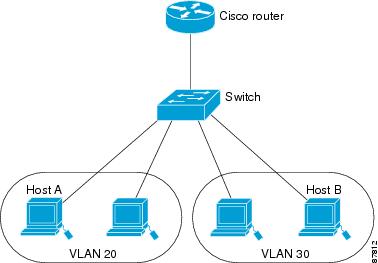
Devices within a single VLAN can communicate directly through any switch. Ports in different VLANs cannot exchange data without going through a routing device or routed interface.
With a standard Layer 2 switch, ports in different VLANs have to exchange information through a router. In the configuration shown in figure below , when Host A in VLAN 20 sends data to Host B in VLAN 30, it must go from Host A to the switch, to the router, back to the switch, and then to Host B.
Figure Connecting VLANs with Layer 2 Switches
Â
Using the Interface Command
To configure a physical interface (port), use the interface global configuration command to enter interface configuration mode and to specify the interface type, slot, and number.
•Type—Fast Ethernet (fastethernet or fa) for 10/100 Ethernet or Gigabit Ethernet (gigabitethernet or gi).
•Slot—The slot number on the switch (always 0 on this switch).
•Port number—The interface number on the switch. The port numbers always begin at 1, starting at the left when facing the front of the switch; for example, fastethernet 0/1, fastethernet 0/2. If there is more than one media type (for example, 10/100 ports and Gigabit Ethernet ports), the port number starts again with the second medium: gigabitethernet 0/1.
You can identify physical interfaces by physically checking the interface location on the switch. You can also use the Cisco IOS show privileged EXEC commands to display information about a specific interface or all the interfaces on the switch. The remainder of this chapter primarily provides physical interface configuration procedures.
Â
Procedures for Configuring Interfaces
Â
These general instructions apply to all interface configuration processes.
Â
Step 1 Enter the configure terminal command at the privileged EXEC prompt:
Switch# configure terminal
Enter configuration commands, one per line. End with CNTL/Z.
Switch(config)#
Â
Step 2 Enter the interface global configuration command. Identify the interface type and the number of the connector. In these examples, Fast Ethernet interface 0/4 is selected, and Gigabit Ethernet 0/1 is selected:
Switch(config)# interface fastethernet0/4
Switch(config-if)#
Switch(config)# interface gigabitethernet0/1
Switch(config-if)#
Step 3 Follow each interface command with the interface configuration commands your particular interface requires. The commands you enter define the protocols and applications that will run on the interface. The commands are collected and applied to the interface when you enter another interface command or enter end to return to privileged EXEC mode.
You can also configure a range of interfaces by using the interface range or interface range macro global configuration commands. Interfaces configured in a range must be the same type and must be configured with the same feature options.
Step 4 After you configure an interface, verify its status by using the show privileged EXEC commands
Enter the show interfaces privileged EXEC command to see a list of all interfaces on or configured for the switch. A report is provided for each interface that the device supports or for the specified interface:
Switch# show interfaces
Vlan1 is up, line protocol is up
Hardware is CPU Interface, address is 0003.fd62.8d40 (bia 0003.fd62.8d40)
Internet address is 172.20.139.142/27
MTU 1500 bytes, BW 1000000 Kbit, DLY 10 usec,
reliability 255/255, txload 1/255, rxload 1/255
Encapsulation ARPA, loopback not set
ARP type: ARPA, ARP Timeout 04:00:00
Last input 00:00:00, output never, output hang never
Last clearing of "show interface" counters never
Input queue: 0/75/0/0 (size/max/drops/flushes); Total output drops: 0
Queueing strategy: fifo
Output queue :0/40 (size/max)
5 minute input rate 2000 bits/sec, 4 packets/sec
5 minute output rate 1000 bits/sec, 2 packets/sec
2832963 packets input, 214073802 bytes, 0 no buffer
Received 21170 broadcasts, 0 runts, 0 giants, 0 throttles
0 input errors, 0 CRC, 0 frame, 0 overrun, 14 ignored
2120022 packets output, 271900223 bytes, 0 underruns
0 output errors, 2 interface resets
0 output buffer failures, 0 output buffers swapped out
FastEthernet0/1 is up, line protocol is up (connected)
Hardware is Fast Ethernet, address is 0003.fd62.8d41 (bia 0003.fd62.8d41)
MTU 1500 bytes, BW 100000 Kbit, DLY 1000 usec,
reliability 255/255, txload 1/255, rxload 1/255
Encapsulation ARPA, loopback not set
Keepalive set (10 sec)
Full-duplex, 100Mb/s
input flow-control is off, output flow-control is off
ARP type: ARPA, ARP Timeout 04:00:00
Last input 00:00:00, output 00:00:00, output hang never
Last clearing of "show interface" counters never
Input queue: 0/75/0/0 (size/max/drops/flushes); Total output drops: 0
Queueing strategy: fifo
Output queue :0/40 (size/max)
5 minute input rate 0 bits/sec, 0 packets/sec
5 minute ouxtput rate 0 bits/sec, 0 packets/sec
1074142 packets input, 81896024 bytes, 0 no buffer
Received 922680 broadcasts, 0 runts, 0 giants, 0 throttles
0 input errors, 0 CRC, 0 frame, 0 overrun, 0 ignored
0 watchdog, 922675 multicast, 0 pause input
0 input packets with dribble condition detected
1547721 packets output, 107609465 bytes, 0 underruns
0 output errors, 0 collisions, 2 interface resets
0 babbles, 0 late collision, 0 deferred
0 lost carrier, 0 no carrier, 0 PAUSE output
0 output buffer failures, 0 output buffers swapped out
Configuring a Range of Interfaces
You can use the interface range global configuration command to configure multiple interfaces with the same configuration parameters. When you enter the interface-range configuration mode, all command parameters that you enter are attributed to all interfaces within that range until you exit this mode.
Beginning in privileged EXEC mode, follow these steps to configure a range of interfaces with the same parameters:
| Â |
Command
|
Purpose
|
|---|---|---|
|
Step 1 |
configure terminal |
Enter global configuration mode. |
|
Step 2 |
interface range {port-range | macro macro_name} |
Enter interface-range configuration mode by entering the range of interfaces (VLANs or physical ports) to be configured. • • • |
|
Step 3 |
 |
You can now use the normal configuration commands to apply the configuration parameters to all interfaces in the range. |
|
Step 4 |
end |
Return to privileged EXEC mode. |
|
Step 5 |
show interfaces [interface-id] |
Verify the configuration of the interfaces in the range. |
|
Step 6 |
copy running-config startup-config |
(Optional) Save your entries in the configuration file. |
When using the interface range global configuration command, note these guidelines:
•Valid entries for port-range:
–vlan vlan-ID - vlan-ID, where VLAN ID is from 1 to 1005
–fastethernet slot/{first port} - {last port}, where slot is 0
–gigabitethernet slot/{first port} - {last port}, where slot is 0
–port-channel port-channel-number - port-channel-number, where port-channel-number is from 1 to 6
•You must add a space between the interface numbers and the hyphen when using the interface range command. For example, the command interface range fastethernet 0/1 - 5 is a valid range; the command interface range fastethernet 0/1-5 is not a valid range.
•The interface range command works only with VLAN interfaces that have been configured with the interface vlan command (the show running-config privileged EXEC command output shows the configured VLAN interfaces). VLAN interfaces that do not appear by using the show running-config command cannot be used with the interface range command.
•All interfaces in a range must be the same type; that is, all Fast Ethernet ports, all Gigabit Ethernet ports, all EtherChannel ports, or VLAN interfaces.
This example shows how to use the interface range global configuration command to enable Fast Ethernet interfaces 0/1 to 0/5:
Switch# configure terminal
Switch(config)# interface range fastethernet0/1 - 5
Switch(config-if-range)# no shutdown
Switch(config-if-range)#
*Oct 6 08:24:35: %LINK-3-UPDOWN: Interface FastEthernet0/1, changed state to up
*Oct 6 08:24:35: %LINK-3-UPDOWN: Interface FastEthernet0/2, changed state to up
*Oct 6 08:24:35: %LINK-3-UPDOWN: Interface FastEthernet0/3, changed state to up
*Oct 6 08:24:35: %LINK-3-UPDOWN: Interface FastEthernet0/4, changed state to up
*Oct 6 08:24:35: %LINK-3-UPDOWN: Interface FastEthernet0/5, changed state to up
*Oct  6 08:24:36: %LINEPROTO-5-UPDOWN: Line protocol on Interface FastEthernet0/05,
changed state to up
*Oct  6 08:24:36: %LINEPROTO-5-UPDOWN: Line protocol on Interface FastEthernet0/3, changed
state to up
*Oct  6 08:24:36: %LINEPROTO-5-UPDOWN: Line protocol on Interface FastEthernet0/4, changed
state to up
This example shows how to use a comma to add different interface type strings to the range to enable all Fast Ethernet interfaces in the range 0/1 to 0/3 and Gigabit Ethernet interfaces 0/1:
Switch# configure terminal
Switch(config)# interface range fastethernet0/1 - 3, gigabitethernet0/1
Switch(config-if-range)# no shutdown
Switch(config-if-range)#
*Oct 6 08:29:28: %LINK-3-UPDOWN: Interface FastEthernet0/1, changed state to up
*Oct 6 08:29:28: %LINK-3-UPDOWN: Interface FastEthernet0/2, changed state to up
*Oct 6 08:29:28: %LINK-3-UPDOWN: Interface FastEthernet0/3, changed state to up
*Oct 6 08:29:28: %LINK-3-UPDOWN: Interface GigabitEthernet0/1, changed state to up
*Oct  6 08:29:29: %LINEPROTO-5-UPDOWN: Line protocol on Interface GigabitEthernet0/ 1,
changed state to up
*Oct  6 08:29:29: %LINEPROTO-5-UPDOWN: Line protocol on Interface FastEthernet0/ 2,
changed state to up
*Oct  6 08:29:29: %LINEPROTO-5-UPDOWN: Line protocol on Interface FastEthernet0/ 3,
changed state to up
If you enter multiple configuration commands while you are in interface-range mode, each command is executed as it is entered. The commands are not batched together and executed after you exit interface-range mode. If you exit interface-range configuration mode while the commands are being executed, some commands might not be executed on all interfaces in the range. Wait until the command prompt reappears before exiting interface-range configuration mode.
Â