Wave energy technologies extract energy directly from surface waves or from pressure fluctuations below the surface. Renewable energy analysts and experts in related fields believe that there is enough energy in ocean waves to provide up to 2 terawatts of electricity. (A terawatt is equal to a trillion watts.)
However, wave energy cannot be harnessed everywhere. Wave power-rich areas of the world include the western coasts of Scotland, northern Canada, southern Africa, and Australia as well as the northeastern and northwestern coasts of the United States. In the Pacific Northwest alone, it is feasible that wave energy could produce 40–70 kilowatts (kW) per 3.3 feet (1 meter) of western coastline.
Wave Generation
Waves are generated by forces that disturb a body of water. They can result from a wide range of forces – the gravitational pull of the sun and the moon, underwater earthquakes and landslides, the movements of boats and swimmers. The vast majority of ocean waves, however, are generated by wind.
Out in the ocean, as the wind blows across a smooth water surface, air molecules push against the water. This friction between the air and water pushes up tiny ridges or ripples on the ocean surface. As the wind continues to blow, these ripples increase in size, eventually growing into waves that may reach many meters in height.
Three factors determine how large wind-generated waves can become. The first factor is wind speed, and the second factor is wind duration, or the length of time the wind blows. The final factor is the fetch, the distance over which the wind blows without a change in direction. The faster the wind, the longer it blows, and the larger the fetch, the bigger the waves that will result. But the growth of wind-generated ocean waves is not indefinite. After a certain point, the energy imparted to the waters by a steady wind is dissipated by wave breaking (often in the form of whitecaps). When this occurs and the waves can no longer grow, the sea state is said to be a ‘fully developed’.
When waves are being generated by strong winds in a storm, the sea surface generally looks very chaotic, with lots of short, steep waves of varying heights. In calm areas far from strong winds, ocean waves often have quite a different aspect, forming long, rolling peaks of uniform shape. For this reason, physical oceanographers differentiate between two types of surface waves: seas and swells. Seas refer to short-period waves that are still being created by winds or are very close to the area in which they were generated. Swells refer to waves that have moved out of the generating area, far from the influence of the winds that made them.
In general, seas are short-crested and irregular, and their surface appears much more disturbed than for swells. Swells, on the other hand, have smooth, well-defined crests and relatively long periods. Swell is more uniform and regular than seas because wave energy becomes more organized as it travel longs distances. Longer period waves move faster than short period waves, and reach distant sites first. In addition, wave energy is dissipated as waves travel (from friction, turbulence, etc.), and short-period wave components lose their energy more readily than long-period components. As a consequence of these processes, swells form longer, smoother, more uniform waves than seas.
Waves are generated by wind passing over the surface of the sea. As long as the waves propagate slower than the wind speed just above the waves, there is an energy transfer from the wind to the waves. Both air pressure differences between the upwind and the lee side of a wave crest, as well as friction on the water surface by the wind, making the water to go into the shear stress causes the growth of the waves.
Wave height is determined by wind speed, the duration of time the wind has been blowing, fetch (the distance over which the wind excites the waves) and by the depth and topography of the seafloor (which can focus or disperse the energy of the waves). A given wind speed has a matching practical limit over which time or distance will not produce larger waves. When this limit has been reached the sea is said to be “fully developed”.
In general, larger waves are more powerful but wave power is also determined by wave speed, wavelength, and water density.
Oscillatory motion is highest at the surface and diminishes exponentially with depth. However, for standing waves (clapotis) near a reflecting coast, wave energy is also present as pressure oscillations at great depth, producing microseisms. These pressure fluctuations at greater depth are too small to be interesting from the point of view of wave power.
The waves propagate on the ocean surface, and the wave energy is also transported horizontally with the group velocity. The mean transport rate of the wave energy through a vertical plane of unit width, parallel to a wave crest, is called the wave energy flux (or wave power, which must not be confused with the actual power generated by a wave power device).
Wave Energy Technologies
The wave energy devices being developed and tested today are highly diverse, and a variety of technologies have been proposed to capture the energy from waves. Some of the more promising designs are undergoing demonstration testing at commercial scales.
Wave technologies have been designed to be installed in the nearshore, offshore, and far offshore locations. While wave energy technologies are intended to be installed at or near the water’s surface, there can be major differences in their technical concept and design. For example, they may differ in their orientation to the waves or in the manner in which they convert energy from the waves.
Although wave power technologies are continuing to develop, there are four basic applications that may be suitable for deployment on the Outer Continental Shelf (OCS): point absorbers, attenuators, overtopping devices, and terminators.
Terminator devices extend perpendicular to the direction of the wave and capture or reflect the power of the wave. These devices are typically onshore or nearshore; however, floating versions have been designed for offshore applications. The oscillating water column is a form of terminator in which water enters through a subsurface opening into a chamber, trapping air above. The wave action causes the captured water column to move up and down like a piston, forcing the air though an opening connected to a turbine to generate power. These devices generally have power ratings of 500 kW to 2 MW, depending on the wave climate and the device dimensions.
- Attenuators are long multisegment floating structures oriented parallel to the direction of the waves. They ride the waves like a ship, extracting energy by using restraints at the bow of the device and along its length. The differing heights of waves along the length of the device causes flexing where the segments connect. The segments are connected to hydraulic pumps or other converters to generate power as the waves move across. A transformer in the nose of the unit steps up the power-to-line voltage for transmission to shore. Power is fed down an umbilical cable to a junction box in the seabed, connecting it and other machines via a common subsea cable to shore.
- A point absorber is a floating structure with components that move relative to each other due to wave action (e.g., a floating buoy inside a fixed cylinder). Point absorbers often look like floating oceanographic buoys. They utilize the rise and fall of the wave height at a single point for energy conversion. The relative up and down bobbing motion caused by passing waves is used to drive electromechanical or hydraulic energy converters to generate power.
- Overtopping devices have reservoirs that are filled by incoming waves, causing a slight buildup of water pressure like a dam. The water is then released, and gravity causes it to flow back into the ocean. The energy of the falling water is used to turn hydro turbines to generate power. Specially built floating platforms can also create electricity by funneling waves through internal turbines and then back into the sea.
Wave Power Data
In deep water where the water depth is larger than half the wavelength, the wave energy flux is
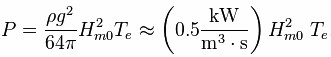
with P the wave energy flux per unit of wave-crest length, Hm0 the significant wave height, Te the wave energy period, ρ the water density and g the acceleration by gravity. The above formula states that wave power is proportional to the wave energy period and to the square of the wave height. When the significant wave height is given in metres, and the wave period in seconds, the result is the wave power in kilowatts (kW) per metre of wavefront length.
Example: Consider moderate ocean swells, in deep water, a few km off a coastline, with a wave height of 3 m and a wave energy period of 8 seconds. Using the formula to solve for power, we get
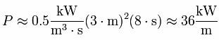
meaning there are 36 kilowatts of power potential per meter of wave crest.
In major storms, the largest waves offshore are about 15 meters high and have a period of about 15 seconds. According to the above formula, such waves carry about 1.7 MW of power across each metre of wavefront.
An effective wave power device captures as much as possible of the wave energy flux. As a result, the waves will be of lower height in the region behind the wave power device.
Wave energy and wave-energy flux – In a sea state, the average(mean) energy density per unit area of gravity waves on the water surface is proportional to the wave height squared, according to linear wave theory:
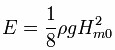
where E is the mean wave energy density per unit horizontal area (J/m2), the sum of kinetic and potential energy density per unit horizontal area. The potential energy density is equal to the kinetic energy, both contributing half to the wave energy density E, as can be expected from the equipartition theorem. In ocean waves, surface tension effects are negligible for wavelengths above a few decimetres.
As the waves propagate, their energy is transported. The energy transport velocity is the group velocity. As a result, the wave energy flux, through a vertical plane of unit width perpendicular to the wave propagation direction, is equal to:

with cg the group velocity (m/s). Due to the dispersion relation for water waves under the action of gravity, the group velocity depends on the wavelength λ, or equivalently, on the wave period T. Further, the dispersion relation is a function of the water depth h. As a result, the group velocity behaves differently in the limits of deep and shallow water, and at intermediate depths – properties of gravity waves on the surface of deep water, shallow water and at intermediate depth, according to linear wave theory
Deep-water characteristics and opportunities – Deep water corresponds with a water depth larger than half the wavelength, which is the common situation in the sea and ocean. In deep water, longer-period waves propagate faster and transport their energy faster. The deep-water group velocity is half the phase velocity. In shallow water, for wavelengths larger than about twenty times the water depth, as found quite often near the coast, the group velocity is equal to the phase velocity.
Wave Energy Conversion Devices
There is a large number of concepts for wave energy conversion; over 1000 wave energy conversion techniques have been patented in Japan, North America, and Europe . Despite this large variation in design, WECs are generally categorized by location and type.
According to location,wave energy convertors are categorized as follows:
- Shoreline devices
- Nearshore devices
- Offshore devices
According to type, wave energy convertors are categorized as follows:
- Attenuators
- Point Absorbers
- Terminators
7 Principles of Wave Energy Extraction
- Provide a point of reaction: Power is captured when wave induced motion is damped. The force resisting the motion results in an equal force in the opposite direction. This has to be opposed by something; no sky hooks allowed.
- The DoF where power is extracted must have a restoring force: There must be a way to restore the change in position due to wave induced motion. Gravity is the simplest method; buoyancy does the job for heave, pitch and roll motion. If power is captured from surge, sway or yaw motions, a restoring force must be supplied by mechanical springs, or by coupling to a motion that has buoyancy.
- Radiated waves capture waves: When the power take off (PTO) system is run in reverse (motoring), the waves generated indicate the potential for capturing ocean waves. Good performance results from radiation of waves that have the same direction of travel, the same amplitude, and the opposite phase, as the waves you want to capture. These are the waves that the incoming wave splits into once it reaches the device: the waves reflected and/or transmitted by the wave energy converter.
- Get the level of damping just right.
- Match natural period to wave period: Radiating a wave which is out of phase with the waves you want to capture is important. At resonance the phase takes care of itself. The options are to design for a natural period that equals the design wave period, to have a range of operating modes with different natural periods, or to use the PTO force to trick the system into behaviour with the desired natural period.
- Size matters: The smaller the device, the narrower the bandwidth of the capture curve, and the lower the natural period. These disadvantages trade off against cost, so clearly size is an important cost of energy consideration.
- Manage losses: Reduce losses (PTO, overheads) in low energy seas; shed loads and power in high energy seas.
Environmental Effects
Common environmental concerns associated with marine energy developments include:
- The risk of marine mammals and fish being struck by tidal turbine blades
- The effects of EMF and underwater noise emitted from operating marine energy devices
- The physical presence of marine energy projects and their potential to alter the behavior of marine mammals, fish, and seabirds with attraction or avoidance
- The potential effect on nearfield and farfield marine environment and processes such as sediment transport and water quality.
Wave Energy Potential
India is estimated to have a potential of 40-60 GW of Wave Energy around it cost with the current state of technology. The wave energy potential is estimated to be 5-15 MW per metre of coastline. There are no big wave energy plants in India except the pilot plant at Vizinjham Fisheries Harbor near Trivandrum in Kerala.
Maharashtra government has built project would generate 15 to 20 kilowatt of electricity located at Borya and Budhal villages in coastal Ratnagiri district. Similar pilot projects exploiting the tidal waves are being undertaken in 15 coastal villages
Sagar Shakthi is a 1 MW OTEC plant built off the Tuticorn coast which utilizes the temperature different wave energy device.
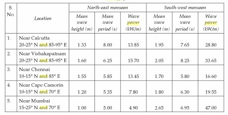
47 kW/mis available off Bombay during Southwest monsoon period. Based on the wave statistics for the southern tip of India, a mean monthly wave power of 4 – 25 kW/m is estimated. The average wave potential along the Indian coast is around 5-10 kW/m. India has a coastline of approximately 7500 km. Even 10% utilization would mean a resource of 3750 –7500 MW.
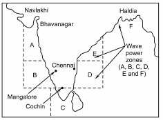
Potential of Indian coastline is illustrated in table below
The 6 zones of the Indian coastline, as divided by the National Institute of Oceanography, Goa in A,B, C,D,E and F and as shown in the following map