When specifying a point, you can enter distances, offsets, and measured intervals.
Direct Distances
You can specify a point by moving the cursor to indicate a direction and then entering the distance. To specify a line length quickly, without entering coordinate values, you can specify a point by moving the cursor to indicate a direction and then entering the distance from the first point. You can enter calculated distances from the QuickCalc calculator. For more information, see Use the QuickCalc Calculator.
You can use direct distance entry to specify points for all commands requiring more than one point. When Ortho mode or polar tracking is on, this method is an efficient way to draw lines of specified length and direction, and to move or copy objects. The direct distance entry method is not available while you are using the temporary override keys for Ortho mode, object snap tracking, or polar tracking.
You can establish a temporary reference point as a base point for offsetting subsequent points. The From command modifier establishes a temporary reference point as a base point for offsetting subsequent points. The From method does not constrain the cursor to orthogonal movement. The From method usually is used in combination with object snaps.
Intervals on Objects
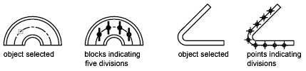
Provides a high-level overview of two options for marking off equal distances along objects. Sometimes you need to create points or insert symbols (blocks) at intervals on an object. You can
- Specify the length of the segments ( MEASURE)
- Specify the number of equal segments ( DIVIDE)
You can measure or divide lines, arcs, splines, circles, ellipses, and polylines. With both methods, you can identify the intervals by inserting either a point or a block. By specifying points, you can use the Node object snap to align other objects at intervals on the measured or divided object. By specifying blocks, you can create precise geometric constructions or insert custom markers. The blocks can rotate at each insertion point.
You cannot insert a block unless it has already been defined within the drawing. Variable attributes within the block are not included when you insert the block references. The points or blocks you draw using MEASURE or DIVIDE are placed in a selection set. Therefore, if you want to edit them immediately, you can use the Previous option of SELECT.
You can mark off equal lengths from one end of a selected object. You can use MEASURE to mark an object at specified intervals. You can mark the intervals with either points or blocks. The last segment of a measured object may be shorter than the interval you specify.
The starting point for measurements or divisions varies with the object type. For lines or open polylines, the starting point is the endpoint closest to the selection point. For closed polylines, it is the polyline start point. For circles, it is at the angle from the center point that is equivalent to the current snap angle. For example, if the snap angle is 0, the circle starts at the three o’clock position and continues counterclockwise.
If the point marker is displayed as a single dot (the default setting), you may not be able to see the measured intervals. You can change the style of the point markers using several methods. To change the point style in a dialog box, you can use DDPTYPE. Alternately, click Format menu ->Point Style. The PDMODE system variable also controls the appearance of point markers. For example, you can change the value to make points appear as crosses. PDSIZE controls the size of point objects.
Divide an Object into Equal Segments
You can divide a selected object into a specified number of equal lengths. You can create points or insert blocks on an object at a specific number of equal intervals. This operation does not actually break an object into individual objects; it only identifies the location of the divisions so that you can use them as geometric reference points.
The starting point for measurements or divisions varies with the object type. For lines or open polylines, the starting point is the endpoint closest to the selection point. For closed polylines, it is the polyline start point. For circles, it is at the angle from the center point that is equivalent to the current snap angle. For example, if the snap angle is 0, the circle starts at the three o’clock position and continues counterclockwise.
If the point marker is displayed as a single dot (the default setting), you may not be able to see the segments. You can change the style of the point markers using several methods. To change the point style in a dialog box, you can use DDPTYPE. Alternately, click Format menu Point Style. The PDMODE system variable also controls the appearance of point markers. For example, you can change the value to make points appear as crosses. PDSIZE controls the size of point objects.
