With parametric drawing, you can add constraints to geometry to ensure that the design conforms to specified requirements. Parametric drawing is a technology that is used for designing with constraints. Constraints are associations and restrictions applied to 2D geometry. There are two general types of constraints
- Geometric constraints control the relationships of objects with respect to each other
- Dimensional constraints control the distance, length, angle, and radius values of objects
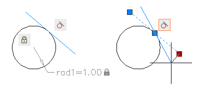
The following illustration displays geometric and dimensional constraints using the default format and visibility.
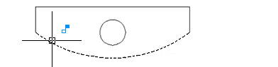
A blue cursor icon always displays when you move the cursor over an object that has constraints applied to it.
In the design phase of a project, constraints provide a way to enforce requirements when experimenting with different designs or when making changes. Changes made to objects can adjust other objects automatically, and restrict changes to distance and angle values. With constraints, you can
- Maintain design specifications and requirements by constraining the geometry within a drawing
- Apply multiple geometric constraints to objects instantly
- Include formulas and equations within dimensional constraints
- Make design changes quickly by changing the value of a variable
It is recommended that you first apply geometric constraints to determine the shape of a design, and then apply dimensional constraints to determine the size of objects in a design.
Design Using Constraints – When you are creating or changing a design, a drawing will be in one of three states
- No constraints are applied to any geometry.
- Some constraints are applied to the geometry.
- Fully constrained. All relevant geometric and dimensional constraints are applied to the geometry. A fully constrained set of objects also needs to include at least one Fix constraint to lock the location of the geometry.
Thus, there are two general methods for designing with constraints
- You can work in an underconstrained drawing and make changes as you go, using a combination of editing commands, grips, and adding or changing constraints.
- You can create and fully constrain a drawing first, and then control the design exclusively by relaxing and replacing geometric constraints, and changing the values in dimensional constraints.
The method that you choose depends on your design practices and the requirements of your discipline. The program prevents you from applying any constraints that result in an overconstrained condition.
Use Constraints with Blocks and Xrefs – You can apply constraints between
- An object in the drawing and an object within a block reference
- An object within a block reference and an object within a different block reference (not between objects within the same block reference)
- The insertion point of an xref and an object or a block, but not to any objects within xrefs
When you apply constraints to block references, the objects contained within the block are automatically available for selection. You do not need to press Ctrl for subobject selection. Adding constraints to a block reference can cause it to move or rotate as a result. Applying constraints to dynamic blocks suppresses the display of their dynamic grips. You can still change the values in a dynamic block using the Properties palette, but to redisplay the dynamic grips, the constraints must first be removed from the dynamic block.
Constraints can be used in block definitions, resulting in dynamic blocks. You can control the size and shape of dynamic blocks directly from within the drawing. For more information, see Add Constraints to Dynamic Blocks.
Remove or Relax Constraints – There are two ways to cancel the effects of constraints when you need to make design changes:
- Delete the constraints individually and later apply new constraints. While the cursor hovers over a geometric constraint icon, you can use the Delete key or the shortcut menu to delete the constraint.
- Relax the constraints temporarily on selected objects to make the changes. With a grip selected or when you specify options during an editing command, tap the Ctrl key to alternate between relaxing constraints and maintaining constraints.
Relaxed constraints are not maintained during editing. Constraints are restored automatically if possible when the editing process is complete. Constraints that are no longer valid are removed. The DELCONSTRAINT command deletes all geometric and dimensional constraints from an object.
Geometric Constraints
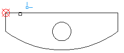
You can specify geometric constraints between 2D objects or points on objects. When you later edit the constrained geometry, the constraints are maintained. Thus, using geometric constraints, you have a method of including design requirements in your drawing. For example, in the illustration below, the following constraints are applied to the geometry.
- Every endpoint is constrained to remain coincident with the endpoint of every adjacent object—these constraints are displayed as small blue squares
- The vertical lines are constrained to remain parallel with each other and to remain equal to each other in length
- The left vertical line is constrained to remain perpendicular to the horizontal line
- The horizontal line is constrained to remain horizontal
- The location of the circle and the horizontal line are constrained to remain fixed in space—these constraints are displayed as lock icons
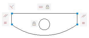
The geometry is not fully constrained, however. Using grips, you can still change the radius of the arc, the diameter of the circle, the length of the horizontal line, and the length of the vertical lines. To specify these distances, you need to apply dimensional constraints. Constraints can be added to segments within a polyline as if they were separate objects.
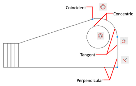
Apply or Remove Geometric Constraints – Geometric constraints associate geometric objects together, or specify a fixed location or angle. For example, you can specify that a line should always be perpendicular to another one, that an arc and a circle should always remain concentric, or that a line should always be tangent to an arc.
When you apply a constraint, two things occur:
- The object that you select adjusts automatically to conform to the specified constraint
- By default, a gray constraint icon displays near the constrained object as shown in the previous illustration, and a small, blue glyph displays with your cursor when you move it over a constrained object
Once applied, constraints permit only those changes to the geometry that do not violate the constraints. This provides a method for exploring design options or making design changes while maintaining the requirements and specifications of the design. The order in which you select two objects when you apply a constraint is important in some cases. Normally, the second object you select adjusts to the first object. For example, when you apply a Perpendicular constraint, the second object you select will adjust to become perpendicular to the first.
You can apply geometric constraints to 2D geometric objects only. Objects cannot be constrained between model space and paper space.
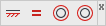
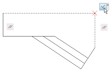
Specify Constraint Points – With some constraints, you specify constraint points on objects instead of selecting the objects. This behavior is similar to that of object snaps, but the locations are limited to endpoints, midpoints, center points, and insertion points. For example, the Coincident constraint can restrict the location of the endpoint of one line to the endpoint of another line.
The following glyph is displayed on the object as you roll over the object.
You use this glyph to confirm whether you are specifying the intended point to constrain.
Use Fix Constraints – A Fix constraint associates a constraint point on an object, or the object itself with a fixed location with respect to the World Coordinate System. It is often advisable to specify a Fix constraint at an important geometric feature. This locks the location of that point or object, and prevents geometry from relocating when you make changes to the design. When you fix an object, the angle of a line, or the center of an arc or circle is also fixed.
Apply Multiple Geometric Constraints – You can apply multiple geometric constraints to objects either manually or automatically. When you want to apply all essential geometric constraints to a design automatically, you can use AUTOCONSTRAIN with the objects that you select in your drawing. This helps constrain the geometric shape of the design—depending on your design, there might be cases where you need to apply additional geometric constraints. AUTOCONSTRAIN also provides settings in which you can specify the following options:
- What geometric constraints to apply
- What order to apply geometric constraints
- What tolerances are used to determine whether objects are horizontal, vertical, or touching
Equal or Fix constraints are not applied with AUTOCONSTRAIN. You must apply these constraints individually. To fully constrain the size and proportions of a design, you will later need to apply dimensional constraints.
Remove Geometric Constraints – A geometric constraint cannot be modified, but you can delete it and apply a different one. Several constraint options, including Delete, are available from the shortcut menu that is displayed when you right-click a constraint icon in the drawing.
Display and Verify Geometric Constraints
You can determine visually what objects are associated with any geometric constraint, or what constraints are associated with any object. Constraint icons provide information about how objects are constrained. A constraint bar displays one or more icons that represent the geometric constraints applied to an object.
You can drag constraint bars when you need to move them out of the way, and you can also control whether they are displayed or hidden.
Verify the Geometric Constraints on Objects – You can confirm the association of geometric constraints with objects in two ways.
- When you roll over a constraint icon on a constraint bar, the objects associated with that geometric constraint are highlighted.
- When you roll over an object that has geometric constraints applied to it, all constraint bars that are associated with the object are highlighted.
These highlighting features simplify working with constraints especially when you have many constraints applied throughout a drawing.
Modify Constrained Objects with Grips – You can modify constrained geometry using grip editing modes. The geometry will maintain all applied constraints. For example, if a line object is constrained to remain tangent to a circle, you can rotate the line and change its length and endpoints, but the line or its extension will remain tangent to the circle.
If the circle was an arc instead, the line or its extension would remain tangent to the arc or its extension.
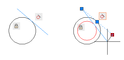
The results of modifying underconstrained objects are based on what constraints have already been applied and the object types involved. For example, if the Radius constraint had not been applied, the radius of the circle would have been modified instead of the tangent point of the line.
The CONSTRAINTSOLVEMODE system variable determines the way an object behaves when constraints are applied or when grips are used to edit it.
Dimensional Constraints
Dimensional constraints control the size and proportions of a design. They can constrain the following
- Distances between objects, or between points on objects
- Angles between objects, or between points on objects
- Sizes of arcs and circles
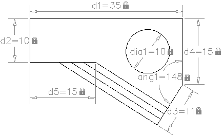
For example, the following illustration includes linear, aligned, angular, and diameter constraints.
If you change the value of a dimensional constraint, all the constraints on the object are evaluated, and the objects that are affected are updated automatically. Also, constraints can be added directly to segments within a polyline as if they were separate objects. The number of decimal places displayed in dimensional constraints is controlled by the LUPREC and AUPREC system variables.
You can easily edit the names, values, and expressions that are associated with dimensional constraints. There are four access points that you can use:
- Double-click the dimensional constraint, select the dimensional constraint and use the shortcut menu, or the TEXTEDIT command.
- Open the Properties palette and select the dimensional constraint
- Open the Parameters Manager and select the dimensional constraint either from the list or from within the drawing
- Customize the Quick Properties palette to display several constraint properties
When you enter the changes, the results will propagate across the drawing immediately.
You can modify a constrained object either by using the triangular grips or the square grips on the associated dimensional constraint. The triangular grips on dimensional constraints provide a way of changing the constraint value while maintaining the constraint. For example, you can change the length of the diagonal line by using the triangular grips on the Aligned dimensional constraint. The diagonal line maintains its angle and the location of one of its endpoints. The square grip on dimensional constraints provides a way of changing the location of the text and other elements. Dynamic dimensional constraints are more limited than annotational dimensional constraints in where the text can be located.
Define Variables and Equations – With the Parameters Manager, you can define custom user variables that you can reference from within dimensional constraints and other user variables. The expressions that you define can include a variety of predefined functions and constants.
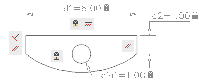
Dimensional constraints maintain specified distances and angles between geometric objects or points on objects. For example, you can specify that the length of a line should always remain at 6.00 units, that the vertical distance between two points be maintained at 1.00 unit, and that a circle should always remain at 1.00 unit in diameter.
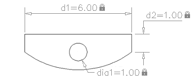
When you apply a dimensional constraint to an object, a constraint variable is automatically created for maintaining the constraint value. By default, these are assigned names such as d1 or dia1, but you can rename them in the Parameters Manager. Dimensional constraints can be created in one of the following forms
- Dynamic constraints
- Annotational constraints
The forms have different purposes. In addition, any dynamic or annotational constraint can be converted to a reference constraint.
Dynamic Constraints – By default, dimensional constraints are dynamic. They are ideal for normal parametric drawing and design tasks. Dynamic constraints have the following characteristics:
- Maintain the same size when zooming in or out
- Can easily be turned on or off globally in the drawing
- Display using a fixed, predefined dimension style
- Position the textual information automatically, and provide triangle grips with which you can change the value of a dimensional constraint
- Do not display when the drawing is plotted
If you need to control the dimension style of dynamic constraints, or if you need to plot dimensional constraints, use the Properties palette to change dynamic constraints to annotational constraints.
You can hide all dynamic constraints globally within a drawing to reduce clutter when you want to work with geometric constraints only, or when you need to continue other work in the drawing. You can turn on their display when needed from the ribbon or with the DYNCONSTRAINTDISPLAY system variable. By default, if you select an object associated with a hidden dynamic constraint, all dynamic constraints associated with that object will display.
Annotational Constraints – Annotational constraints are useful when you want dimensional constraints to have the following characteristics
- Change their size when zooming in or out
- Display individually with layers
- Display using the current dimension style
- Provide grip capabilities that are similar to those on dimensions
- Display when the drawing is plotted
To display the text used in annotational constraints in the same format as used in dimensions, set the CONSTRAINTNAMEFORMAT system variable to 1. After plotting, you can use the Properties palette to convert annotational constraints back to dynamic constraints.
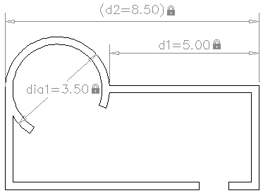
Reference Constraints – A reference constraint is a driven dimensional constraint, either dynamic or annotational. This means that it does not control the associated geometry, but rather reports a measurement similar to a dimension object. You use reference constraints as a convenient way to display measurements that you would otherwise have to calculate. For example, the width in the illustration is constrained by the diameter constraint, dia1, and the linear constraint, d1. The reference constraint, d2, displays the total width but does not constrain it. The textual information in reference constraints is always displayed within parentheses.
You can set the Reference property in the Properties palette to convert a dynamic or annotational constraint to a reference constraint. You cannot change a reference constraint back to a dimensional constraint if doing so would overconstrain the geometry.
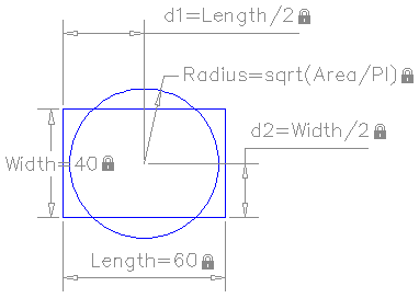
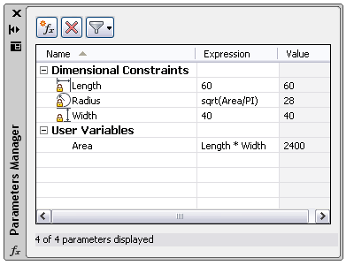
You can control geometry using mathematical expressions that include the names of dimensional constraints, user variables, and functions. Formulas and equations can be represented either as expressions within dimensional constraints or by defining a user variables. For example, the following illustration represents a design that constrains a circle to the center of the rectangle with an area equal to that of the rectangle.
The Length and Width dimensional constraints are set to constants. The d1 and d2 constraints are simple expressions that reference the Length and Width. The Radius dimensional constraint is set to an expression that includes the square root function, parentheses to determine the precedence of operations, the Area user variable, the division operator, and the constant, PI. These parameters are all displayed in the Parameters Manager.
