To specify a new point location, you can combine coordinate values from several points or you can specify offsets from existing objects.
Combine Coordinate Values (Coordinate Filters)
You can use coordinate filters to extract one coordinate value at a time from locations on existing objects. Coordinate filters specify a new coordinate location by using the X value from one location, the Y value of a second location, and, for 3D coordinates, the Z value of a third location. When used with object snaps, coordinate filters extract coordinate values from an existing object.
Coordinate filters are commonly used to locate the center of a rectangle and to locate the projection of a 3D point on the XY plane of the UCS. To specify a filter at the command prompt, enter a period and one or more of the letters X, Y, and Z. The next entry is limited to a specific coordinate value. An example of use of Coordinate Filters in 2D , is as
In the following illustration, the hole in the holding plate was centered in the rectangle by extracting the X,Y coordinates from the midpoints of the plate’s horizontal and vertical line segments.
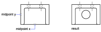
Here is the command prompt sequence:
Command: circle
Specify center point for circle or [3P/2P/Ttr (tangent tangent radius)]: .x
of: mid
of: Select the horizontal line on the lower edge of the holding plate
of: (need YZ): mid
of: Select the vertical line on the left side of the holding plate
of: Diameter/<Radius> Specify the radius of the hole
Coordinate filters work only when the program prompts you for a point. If you try to use a coordinate filter at the command prompt, you see an error message.
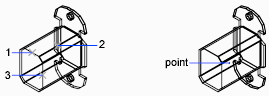
An example of use of Coordinate Filters in 3D – This example shows how to use coordinate filters to create a point object at the center (centroid) of a 3D object. Hidden lines have been removed for clarity. The X value of the new point is extracted from the first location specified, the Y value from the second location, and the Z value from the third. The three values are combined to form the coordinate values of the new point.
Command: point
Point: .x
of mid
of select object (1)
(need YZ): .y
of mid
of select object (2)
(need Z): mid
of select object (3)
Object Snap Tracking
You can draw objects at specific angles or in specific relationship to other objects along specified directions called alignment paths. AutoTrack™ helps you draw objects at specific angles or in specific relationships to other objects. When you turn on AutoTrack, temporary alignment paths help you create objects at precise positions and angles. AutoTrack includes two tracking options: polar tracking and object snap tracking.
You can toggle AutoTrack on and off with the Polar and Otrack buttons on the status bar. Use temporary override keys to turn object snap tracking on and off or to turn off all snapping and tracking. See the keyboard illustration in Override Object Snap Settings. Object snap tracking works in conjunction with object snaps. You must set an object snap before you can track from an object’s snap point.
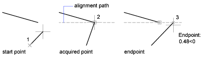
Object Snap Tracking – Use object snap tracking to track along alignment paths that are based on object snap points. Acquired points display a small plus sign (+), and you can acquire up to seven tracking points at a time. After you acquire a point, horizontal, vertical, or polar alignment paths relative to the point are displayed as you move the cursor over their drawing paths. For example, you can select a point along a path based on an object endpoint or midpoint or an intersection between objects.
In the following illustration, the Endpoint object snap is on. You start a line by clicking its start point (1), move the cursor over another line’s endpoint (2) to acquire it, and then move the cursor along the horizontal alignment path to locate the endpoint you want for the line you are drawing (3).
Change Object Snap Tracking Settings – By default, object snap tracking is set to orthogonal. Alignment paths are displayed at 0, 90, 180, and 270 degrees from acquired object points. However, you can use polar tracking angles instead.
For object snap tracking, object points are automatically acquired. However, you can choose to acquire points only when you press SHIFT.
Change Alignment Path Display – You can change how AutoTrack displays alignment paths, and you can change how object points are acquired for object snap tracking. By default, alignment paths stretch to the end of the drawing window. You can change their display to abbreviated lengths, or no length.
As you use AutoTrack (polar tracking and object snap tracking), you will discover techniques that make specific design tasks easier. Here are a few you might try.
- Use Perpendicular, End, and Mid object snaps with object snap tracking to draw to points that are perpendicular to the end and midpoints of objects.
- Use the Tangent and End object snaps with object snap tracking to draw to points that are tangent to the endpoints of arcs.
- Use object snap tracking with temporary tracking points. At a point prompt, enter tt, then specify a temporary tracking point. A small + appears at the point. As you move your cursor, AutoTrack alignment paths are displayed relative to the temporary point. To remove the point, move the cursor back over the +.
- After you acquire an object snap point, use direct distance to specify points at precise distances along alignment paths from the acquired object snap point. To specify a point prompt, select an object snap, move the cursor to display an alignment path, then enter a distance at the command prompt. The direct distance entry method is not available while you are using the temporary override key for object snap tracking.
- Use the Automatic and SHIFT to Acquire options set on the Drafting tab of the Options dialog box to manage point acquisition. Point acquisition is set to Automatic by default. When working in close quarters, press SHIFT to temporarily avoid acquiring a point.
Track to Offset Point Locations (Tracking)
You can use tracking to specify a point by offsetting vertically and horizontally from a series of temporary points. You can use the tracking method whenever you are prompted for a point. Tracking uses the pointing device to specify a point by offsetting vertically and horizontally from a series of temporary points. When you start tracking and specify an initial reference point, the next reference point is constrained to a path that extends vertically or horizontally from that point. The direction of the offset is indicated by the rubber-band line. You change the direction of the offset by moving the cursor through the reference point. You can track as many points as you need. Typically, you use tracking in combination with object snaps or direct distance entry.
For example, you can use tracking to find the center point of a rectangle without using construction lines. Start tracking, and specify the midpoint of a horizontal line. Drag the cursor vertically and specify the midpoint of a vertical line (2). Press ENTER to accept the point (3) at the center of the rectangle.
