Several tools are available that you can use to restrict or lock the movement of your cursor. To enhance drawing speed and efficiency, you can display and snap to a rectangular grid. You can also control its spacing, angle, and alignment.
The grid is a rectangular pattern of dots or lines that extends over the area you specify as the grid limits. Using the grid is similar to placing a sheet of grid paper under a drawing. The grid helps you align objects and visualize the distances between them. The grid is not plotted.
Snap mode restricts the movement of the crosshairs to intervals that you define. When Snap mode is on, the cursor seems to adhere, or “snap,” to an invisible rectangular grid. Snap is useful for specifying precise points with the arrow keys or the pointing device. Grid mode and Snap mode are independent but are often turned on at the same time.
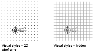
Control the Display Style and Area of the Grid – You can display the grid either as a rectangular pattern of dots or as rectangular pattern of lines. The grid displays dots only when the current visual style is set to 2D Wireframe, otherwise the grid displays lines. A lined grid is displayed for all visual styles while working in 3D. There are several methods to change the current visual style, including the VSCURRENT command.
By default, the X and Y axes of the UCS display in a different color than the grid lines. You can control the color in the Drawing Window Colors dialog box. This dialog box is accessible from the Drafting tab in the Options dialog box.
The LIMITS command controls the drawing area covered by the grid. As an option, you can override the limits to make the grid cover the entire XY plane of the user coordinate system (UCS). You can access this option in the Drafting Settings dialog box or use the GRIDDISPLAY system variable. When you use dynamic UCS, the grid limits are set automatically relative to the size of the selected face of the solid and the drawing area available.
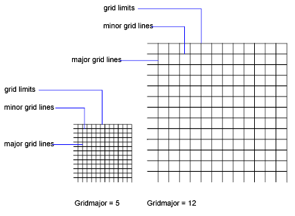
Control the Frequency of Major Grid Lines – If the grid is displayed as lines rather than dots, darker lines called major grid lines display at intervals. When working in decimal units or with feet and inches, major grid lines are especially useful for measuring distances quickly. You can control the frequency of major grid lines in the Drafting Settings dialog box.
To turn off the display of major grid lines, set the frequency of major grid lines to 1. If the grid is displayed as lines, the grid limits are displayed also as darker lines. Do not confuse these boundaries with major grid lines. When the grid is displayed as lines and SNAPANG is set to a value other than 0, the grid will not display. SNAPANG does not affect the display of the dotted grid.
Change the Grid Dynamically During Zooming – If you zoom in or out of your drawing, the grid spacing is adjusted automatically to be more appropriate for the new magnification. This is called adaptive grid display.
For example, if you zoom way out, the density of displayed grid lines reduces automatically. Conversely, if you zoom way in, additional grid lines display in the same proportion as the major grid lines.
Change Grid and Snap Spacing – As you work, you can turn Grid and Snap mode on and off, and you can change the grid and snap spacing. You can turn Snap mode on and off temporarily by using an override key.
Snap spacing does not have to match grid spacing. For example, you might set a wide grid spacing to be used as a reference but maintain a closer snap spacing for accuracy in specifying points.
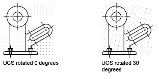
Change the Grid and Snap Angle and Base – If you need to draw along a specific alignment or angle, you can change the grid and snap angle by rotating the user coordinate system (UCS). This rotation realigns the crosshairs on the screen to match the new angle. In the following example, the UCS is rotated 30 degrees to match the angle of the anchor bracket.
The grid and snap points are always aligned with the UCS origin. If you need to shift the grid and grid snap origin, move the UCS.
Orthogonal Locking (Ortho Mode)
You can restrict cursor movement to horizontal and vertical for convenience and precision when creating and modifying objects. As you create or move objects, you can use Ortho mode to restrict the cursor to the horizontal or vertical axis. As you move the cursor, the rubber-band line follows the horizontal or vertical axis, whichever is nearest the cursor.
The orientation of the current user coordinate system (UCS) determines the horizontal and vertical directions. In 3D views, Ortho mode additionally restricts the cursor to the up and down directions. In that case, the tooltip displays a +Z or -Z for the angle. Use direct distance entry with Ortho mode turned on to create orthogonal lines of specified lengths or to move objects specified distances.
You can turn Ortho on and off at any time during drawing and editing. Ortho is ignored when you enter coordinates or specify an object snap. To turn Ortho on or off temporarily, hold down the temporary override key, SHIFT. While you use the temporary override key, the direct distance entry method is not available. If turned on, the isometric snap setting takes priority over the UCS in determining horizontal and vertical directions.
Polar Tracking and PolarSnap
Polar tracking restricts cursor movement to specified angles. PolarSnap restricts cursor movement to specified increments along a polar angle. When you are creating or modifying objects, you can use polar tracking to display temporary alignment paths defined by the polar angles you specify. In 3D views, polar tracking additionally provides an alignment path in the up and down directions. In that case, the tooltip displays a +Z or -Z for the angle.
Polar angles are relative to the orientation of the current user coordinate system (UCS) and the setting for the base angle convention in a drawing. The angle base direction is set in the Drawing Units dialog box.
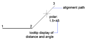
Use PolarSnap™ to snap to specified distances along the alignment path. For example, in the following illustration you draw a two-unit line from point 1 to point 2, and then draw a two-unit line to point 3 at a 45-degree angle to the line. If you turn on the 45-degree polar angle increment, an alignment path and tooltip are displayed when your cursor crosses the 0 or 45-degree angle. The alignment path and tooltip disappear when you move the cursor away from the angle.
As you move your cursor, alignment paths and tooltips are displayed when you move the cursor near polar angles. The default angle measurement is 90 degrees. Use the alignment path and tooltip to draw your object. You can use polar tracking with Intersection and Apparent Intersection object snaps to find where a polar alignment path intersects another object.
Ortho mode and polar tracking cannot be on at the same time. Turning on polar tracking turns off Ortho mode. Similarly, PolarSnap and grid snap cannot be on at the same time. Turning on PolarSnap turns off grid snap.
Specify Polar Angles (Polar Tracking) – You can use polar tracking to track along polar angle increments of 90, 60, 45, 30, 22.5, 18, 15, 10, and 5 degrees, or you can specify other angles. The following illustration shows the alignment paths displayed as you move your cursor 90 degrees with the polar angle increment set to 30 degrees.
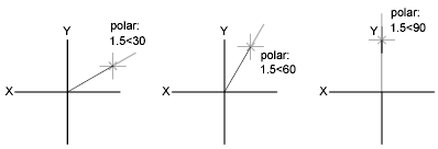
The orientation of 0 depends on the angle you set in the Drawing Units dialog box ( UNITS). The direction of snap (clockwise or counterclockwise) depends on the units direction you specify when setting units of measurement. You can turn polar tracking on and off temporarily by using an override key. The direct distance entry method is not available while you are using the temporary override key for polar tracking.
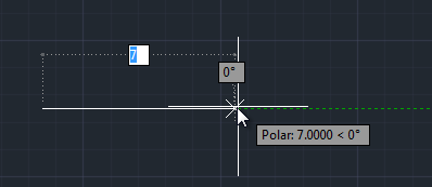
Specify Polar Distances (PolarSnap) – PolarSnap restricts cursor movement to increments of a polar distance you specify. For example, if you specify a length of 4 units, the cursor snaps from the first point specified to lengths of 0, 4, 8, 12, 16, and so on. As you move your cursor, a tooltip indicates the nearest PolarSnap increment. To restrict point entry to polar distances, both polar tracking and Snap mode (set to PolarSnap) must be on. You can turn off all snapping and tracking temporarily by using an override key.
Lock an Angle for One Point (Angle)
You can specify an angle override that locks the cursor for the next point entered. To specify an angle override, enter a left angle bracket (<) followed by an angle whenever a command asks you to specify a point. The command prompt sequence below shows a 30-degree override entered during a LINE command.
Command: line
Specify first point: Specify a start point for the line
Specify next point or [Undo]: <30
Angle Override: 30
Specify next point or [Undo]: Specify a point
The angle you specify will lock the cursor, overriding Grid Snap, Ortho mode, and PolarSnap. Coordinate entry and object snaps have precedence over an angle override.
Grid Mode
To enhance drawing speed and efficiency, you can display a rectangular grid. You can also control its spacing, angle, and alignment. And just like the grid found on engineering graph paper, the grid will not appear when you print or plot your drawing.
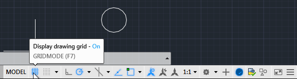
When you first start the program, the grid is toggled on by default. You can toggle the grid on and off using the Display drawing grid button on the Status bar. When you move the cursor over this button, you can see that the grid is currently on. Click the button to toggle it off. The grid disappears from the drawing area, the button changes color, and the tooltip shows that the grid is now off. Click to toggle the grid on again.
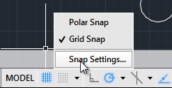
The button on the Status bar to the right of the Display drawing grid button is the Snap mode button. The grid and snap mode are closely related. To adjust the spacing, angle, and alignment of the grid, click the arrow to the right of the Snap mode button and choose Snap Settings… to display the Snap and Grid.
Snap Mode
Snap mode restricts cursor movement to specified intervals.
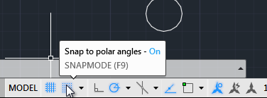
Snap mode is initially toggled off by default. You can toggle snap mode on and off using the Snap 0mode button on the Status bar. When you move the cursor over this button, you can see that snap mode is currently off. Click this button to toggle it on. The button changes color and the tooltip shows that snap mode is now on. With the snap mode turned on, if no command is active, the cursor still continues to move freely. But this changes as soon as you start a command.
For example, on the Home ribbon, in the Draw panel, click the Line tool and then click to specify the first point of the line. When the program prompts you to specify the next point, notice that the cursor continues to move smoothly until you move the cursor so that the next point is either perfectly horizontal or perfectly vertical from the first point. When the line you are about to create aligns with the X- or Y-axis, the cursor now snaps to precise 1-unit increments. This is called polar snap. When the snap mode is set to use polar snap, the cursor snaps to precise snap increments only.
