Create a section plane that can be modified and moved to achieve the cross section view that you need. With the SECTIONPLANE command, you can create one or more section objects and place them throughout a 3D model (3D solids, surfaces, or mesh). By activating live sectioning, you can then view transient cuts in the 3D model as you move the section object through it. The 3D objects themselves do not change.
Set the Cross-Section with the Section Plane Indicator – Section objects have a transparent section plane indicator that acts as a cutting plane. This plane can be moved through a 3D model that is composed of 3D solids, surfaces, or regions to obtain different section views.
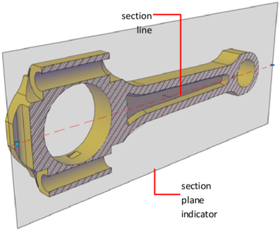
Store Properties in Section Lines – The section plane contains a section line that stores section object properties. You can create multiple section objects to store different properties. For example, one section object can display a hatch pattern at the section plane intersection. Another section object can display a specific linetype for the boundary of the intersected area.
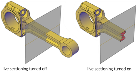
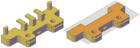
Analyze the Model with Live Sectioning – With live sectioning, you can dynamically analyze the interior details of 3D objects by moving and adjusting the section plane. You can specify whether to hide, or cut away, the portion of the model that is on the viewing side of the section plane indicator.
Save and Share Section Images – After you create a sectional view, you can generate an accurate 2D or 3D block from the 3D model. These blocks can be analyzed or checked for clearances and interference conditions. They can also be dimensioned, or used as wireframe or rendered illustrations in documentation and presentation drawings.
You can also save each section object as a tool on the tool palette. That way, you can avoid resetting properties each time you create a section object.
Create Section Objects
Create cross sections to show interior details of 3D objects. With the SECTIONPLANE command, you create a section object that acts as a cutting plane through solids, surfaces, meshes, or regions. Then turn on live sectioning to move the section object through the 3D model to reveal its inner details in real time. You can align a section object using several methods.
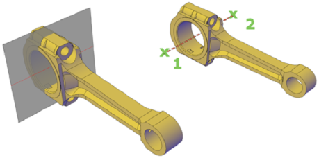
Align the Section Plane to a 3D Face – One way to set the section plane is to click the face of an existing 3D object. (As you move the cursor, a dotted outline indicates the side of the plane to be selected.) The section plane is automatically aligned to the plane of the face you select.
Create a Straight Cutting Plane – Pick two points to create a straight cutting plane.
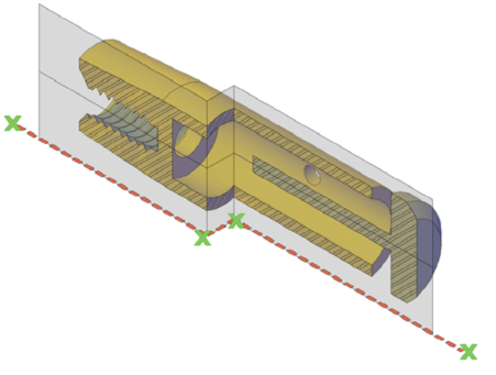
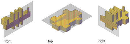
Add a Jogged Segment – The section plane can be a straight line or it can have multiple or jogged sections. For example, a section containing a jog is one that cuts away a pie slice-shaped wedge from a cylinder. Create a section line that has jogged segments by using the Draw Section option to pick multiple points throughout the 3D model. Create Orthographic Sections – You can align section objects to a specified orthographic orientation of the current UCS, such as front, back, bottom, top, left, or right.
Orthographic section planes are placed so that they pass through the center of the 3D extents of all 3D objects in the drawing.
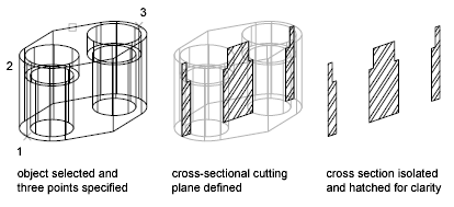
Create a Region to Represent the Cross Section – With the SECTION command, you can create a 2D region object that represents a planar cross section through a 3D solid object. You do not have live sectioning capabilities when you use this legacy method to create cross sections.
Define the plane of the cross section using one of the following methods:
- Specify three points.
- Specify a 2D object such as a circle, ellipse, arc, spline, or polyline.
- Specify a view.
- Specify the Z axis.
- Specify the XY, YZ, or ZX plane.
The new region that represents the cross-sectional plane is placed on the current layer.
Flattened View
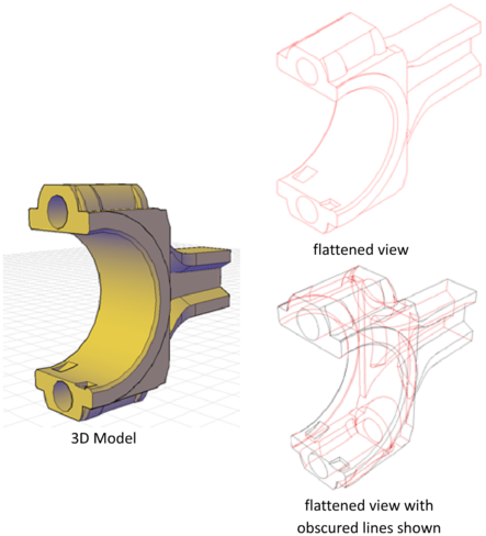
With the FLATSHOT command, you can create a flattened, 2D representation of the 3D model projected onto the XY plane. The resulting objects can be inserted as a block or saved as a separate drawing. The process is like taking a photograph of the entire 3D model and then laying the photograph flat. This feature is useful for creating technical illustrations.
The flatshot process works only in model space. Start by setting up the view you want, including orthographic or parallel views. All 3D objects in the model space viewport are captured. Therefore, be sure to place the objects you do not want captured on layers that are turned off or frozen.
As you create the block, you can control how hidden lines are displayed by adjusting the Foreground and Obscured Lines settings in the Flatshot dialog box. For best results with mesh objects, clear the Show box under Obscured Lines so that hidden lines are not represented.
Three-dimensional objects that have been sectioned are captured in their entirety, as if they had not been sectioned.
