Three-dimensional modeling tools range from entering precise measurements in the Properties palette, to more free-form methods such as grip and gizmo editing. Some methods are specific to 3D solids or meshes. Other methods are shared.
Convert to Other Object Types
In many cases, you can convert from one object type to another to take advantage of specific editing capabilities. For example you can convert selected surfaces, solids, and legacy mesh types to mesh objects so that you can take advantage of smoothing and modeling capabilities.
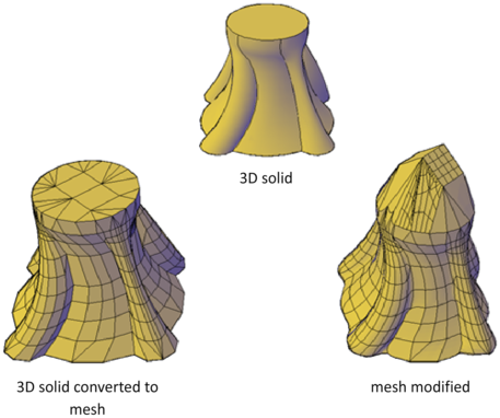
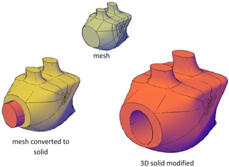
Similarly, you can convert mesh to 3D solids and surfaces to accomplish some composite object modeling tasks that are available only for those objects. Conversion is often offered as a choice when you start activities that are available only for solids and surfaces.
View Your Model from All Angles
When you work with any 3D object, you can easily make changes that are not accurately reflected in the current view. To ensure that your modifications conform to your expectations, make sure you understand and use the following:
- Manipulate the 3D workplane (UCS). To understand how your model is projected in 3D space, learn how to use the X, Y, and Z axes. See Specify Workplanes in 3D (UCS).
- Rotate the view to display the model from different viewpoints. Several navigation tools, including 3D Orbit and the ViewCube, are available to help you rotate around your workspace. See Use Viewing Tools.
Display multiple viewports. Set up two or more viewports with different viewing angles and visual styles. When you make a change in one viewport, you can see its impact from several viewpoints at the same time.
Modify Properties of 3D Objects
Modify 3D objects by changing their settings in the Properties palette.
As with other objects, you can modify the properties of 3D objects such as solids, surfaces, and mesh. In addition, you can modify specific components, known as subobjects: faces, edges, and vertices.
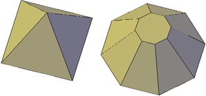
Modify the Primitive Shapes – Primitive solid forms include basic shapes such as boxes, wedges, pyramids, spheres, cylinders, cones, and tori. Each type of primitive solid has unique properties. By changing settings in the Properties palette, you can modify basic size, height, and shape characteristics. For example, to change a four-sided pyramid that ends in a point to an eight-sided pyramid that ends in a planar surface (pyramid frustum), update the Top Radius and Sides properties.
Set Whether to Retain Compound Object History – With 3D solids that have been recombined to form compound objects, you can choose to retain the history subobject, which represents components that have been removed. The Properties palette controls the availability and display of these histories. See Work with Complex 3D Solids and Surfaces.
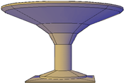
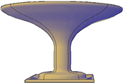
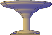
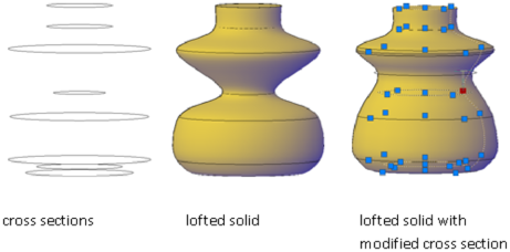
Modify Loft Settings – For lofted solids or surfaces, you can modify such properties as the number of isolines and how the profile passes through the cross sections. (These properties are set in the Loft Settings dialog box during the loft operation.) The Surface Normals property settings change the overall shape of the lofted object.
Ruled: Specifies that the solid or surface is ruled between the cross sections and has sharp edges at the cross sections.
Smooth. Specifies that a smooth solid or surface is interpolated between the cross sections and has sharp edges at the start and end cross sections. The adjacent cross sections control the tangent direction.

First Normal: Specifies that the surface normal is perpendicular to the first cross section.

Last Normal: Specifies that the surface normal is perpendicular to the last cross section.

Ends Normal: Specifies that the surface normal is perpendicular to both the first and last cross sections.
All Normal: Specifies that the surface normal is perpendicular to all cross sections.
Use Draft Angles: Controls the draft angle of the first and last cross sections of the lofted solid or surface. The following variables control the draft angle settings: LOFTANG1, LOFTANG2, LOFTMAG1, and LOFTMAG2.

Modify 3D Object and Subobject Properties – You can modify the properties of the 3D solid, surface, and mesh object in the Properties palette. In addition, you can modify specific properties of individual subobjects, such as faces, edges, and vertices. Different properties are available for different types of subobjects.
In some cases, the application of properties can differ. depending on the object type. For example, you can modify the properties of mesh faces, including their color. However, the color appearance of a mesh face might differ from the equivalent color on a 3D solid face. This difference occurs because changing the color of a face modifies the diffuse color of the face, but not the ambient color (which is derived from the mesh material property). To obtain a closer match between the color of 3D solid and mesh faces, you can add lights and turn off the default lighting (which disables ambient lighting). You can also try assigning a material that has the same ambient and diffuse color. For more information see Create Materials.
Modify Mesh Forms by Changing Properties – Mesh objects have additional properties that control the level of smoothness and creases. Crease properties of face, edge, and vertex subobjects are also reflected in the Properties palette.
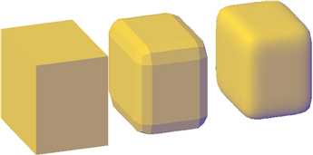
Level of Smoothness. Smooths or sharpens the edges of a mesh object.
Crease Type: Specifies the presence of a crease (or sharpened edge) and the effect of smoothing. Smoothing does not affect a crease with a value of Always. A crease set to By Level retains its sharpness until the mesh object is smoothed to the specified crease level.
Crease Level: When a crease is set to By Level, indicates the smoothing level at which the crease starts to lose its sharpness.
3D Subobjects
A subobject is a face, edge or vertex of a solid, surface, or mesh object.
Select Subobjects – To select a face, edge, or vertex of a 3D object, press Ctrl as you select the object. Selected subobjects display different types of grips, depending on the subobject type.
You can select one or more subobjects on any number of 3D objects. The selection set can include more than one type of subobject. Press Ctrl to select subobjects at the selection prompts of the MOVE, ROTATE, SCALE, and ERASE commands.
You can remove an item from the selection set by pressing the Shift key and selecting it again.
Select Subobjects on Composite 3D Solids – Press and hold Ctrl to select faces, edges, and vertices on composite solids. If the History property of the composite solid is set to Record, the first “pick” might select the history subobject. (The history subobject is the portion of the original object that was removed during the union, subtract, or intersect operation.) Continue to hold down Ctrl and pick again to select a face, edge, or vertex on the original form.
Cycle Through Multiple Subobjects – Selection sets can contain any number of 3D solids, surfaces, meshes, and subobjects. In 3D views, some objects or subobjects might be hidden behind others. You can press Ctrl+Spacebar to cycle through the hidden subobjects until the object you want to select is highlighted.
For example, when you select faces on a box, the face in the foreground is detected first. To select a hidden face, press the Spacebar (with Ctrl still pressed). Release the Spacebar and click to select the face.
For best results, make sure that Selection Preview is turned on in the Options dialog box. If selection preview is turned off, you can cycle through hidden subobjects by pressing Ctrl+Spacebar as you click until the subobject is selected.
Turn on the Subobject Selection Filter – Selecting a specific type of subobject can be difficult on complex objects, such as meshes. You can limit the selection to a face, edge, vertex, or history subobject by setting a subobject selection filter.

Stored in the SUBOBJSELECTIONMODE system variable, this setting can be changed from the shortcut menu or on the ribbon.
Use Grips to Edit 3D Solids and Surfaces – Use grips to change the size and shape of some individual solids and surfaces. The method you use to manipulate the 3D solid or surface depends on the type of object and the method used to create it.
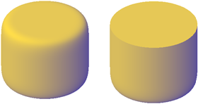
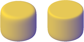
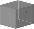
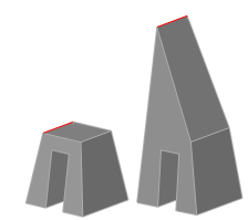
Primitive Solid Forms and Polysolids – You can drag grips to change the shape and size of primitive solids and polysolids. For example, you can change the height and base radius of a cone without losing the overall cone shape. Drag the top radius grips to transform the cone to a flat-topped, frustum cone.
Extruded Solids and Surfaces – You can convert 2D objects to solids and surfaces with the EXTRUDE command. When selected, extruded solids and surfaces display grips on their profiles. A profile is the original outline that defines the shape of the extruded solid or surface. Drag profile grips to modify the overall shape of the object.
If the extrusion was created along a sweep path, the path can be manipulated with grips. If a path was not used, you can modify the height of the object using a grip at the top of the extruded solid or surface.
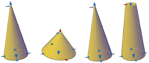
Swept Solids and Surfaces – Swept solids and surfaces display grips on the swept profile as well as on the sweep path. You can drag these grips to modify the solid or surface.
When you click and drag a grip on the profile, the changes are constrained to the plane of the profile curve.
Lofted Solids and Surfaces – Depending on how a lofted solid or surface was created, the solid or surface displays grips on the following, defining lines or curves:
- Cross section
- Path
Drag grips on any of the defining lines or curves to modify the shape. If the lofted object contains a path, you can only edit the portion of the path that is between the first and last cross sections.
You cannot use grips to modify lofted solids or surfaces that are created with guide curves.
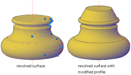
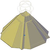
Revolved Solids and Surfaces – Revolved solids and surfaces display grips on the revolved profile at the start of the revolved solid or surface. You can use these grips to modify the profile of the solid of surface. A grip is also displayed at the axis of revolution endpoint. You can relocate the axis of revolution by dragging the grip to another location.
Gizmos
Gizmos help you move, rotate, or scale a set of objects along a 3D axis or plane.
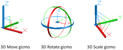
There are three types of gizmos
- 3D Move gizmo. Relocates selected objects along an axis or plane.
- 3D Rotate gizmo. Rotates selected objects about a specified axis.
- 3D Scale gizmo. Scales selected objects along a specified plane or axis, or uniformly along all 3 axes.
By default, gizmos are displayed automatically when you select an object or subobject in a view that has a 3D visual style. Because they constrain modifications along specific planes or axes, gizmos help ensure more predictable results. You can specify which gizmos are displayed when an object is selected, or you can suppress their display.
Display Gizmo – Gizmos are available only in 3D views that are set to use a 3D visual style such as 3D Hidden. You can set the gizmo to be displayed automatically when you select a 3D object or subobject. Gizmos are also displayed during the 3DMOVE, 3DROTATE, and 3DSCALE commands.
If the visual style is set to 2D Wireframe, entering 3DMOVE, 3DROTATE, or 3DSCALE automatically converts the visual style to 3D Wireframe.
By default, the gizmo is initially placed in the center of the selection set. However, you can relocate it anywhere in 3D space. The center box (or base grip) of the gizmo sets the base point for the modification. This behavior is equivalent to temporarily changing the position of the UCS as you move or rotate the selected objects. The axis handles on the gizmo constrain the movement or rotation to an axis or plane.
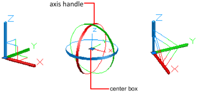
For best results, use object snaps to locate the grip center box.
Switch Between the Gizmos – Whenever you select an object in a 3D view, the default gizmo is displayed. You can select a different default on the ribbon, or change the value of the the DEFAULTGIZMO system variable. You can also suppress the display of gizmos when objects are selected.
After the gizmo is active, you can also switch to a different type of gizmo. The switching behavior differs, depending on when you select the objects:
- Select objects first. If a gizmo operation is in progress, you can press the Spacebar repeatedly to cycle through the other gizmo types. When you switch gizmos this way, the gizmo activity is constrained to the originally selected axis or plane. During a gizmo operation, you can also select a different gizmo type on the shortcut menu.
- Run the command first. When you start the 3D Move, 3D Rotate, or 3D Scale operation before selecting objects, the gizmo is placed at the center of the selection set. Use the Relocate Gizmo option on the shortcut menu to relocate the gizmo anywhere in 3D space. You can also choose a different type of gizmo on the shortcut menu.
Change the Gizmo Settings – The following settings affect the display of gizmos:
Default gizmo. The DEFAULTGIZMO system variable specifies which gizmo is displayed by default when an object is selected in a view with a 3D visual style. You can turn off display of the gizmo. This setting is also available on the ribbon.
- Default location. The GTLOCATION system variable sets the default location of the gizmo. The gizmo can be displayed at the center of the selection set (default), or it can be positioned at the 0,0,0 coordinates of the current UCS.
- Automatic display. The GTAUTO system variable sets whether gizmos are displayed automatically whenever you select objects in a 3D view that is set to a 3D visual style (default). If you turn off this system variable, the grips are not displayed until the gizmos are active.
- Conversion of move, rotate, and scale operations from 2D to 3D. Turn on the GTDEFAULT system variable to start the 3DMOVE, 3DROTATE, or 3DSCALE command automatically when the MOVE, ROTATE, or SCALE command is started in a 3D view. This system variable is turned off by default.
- Active status of subobject grips. If you press Ctrl+click a subobject, the GRIPSUBOBJMODE system variable sets whether the subobject grips are active immediately. Setting subobject grips to be active upon selection helps you modify groups of mesh subobjects without selecting them again.
Move, Rotate, and Scale 3D Subobjects
Use the same methods to modify a face, edge, or vertex that you use to modify the entire object:
- Drag grips
- Use gizmos ( 3DMOVE, 3DROTATE, and 3DSCALE)
- Enter object editing commands ( MOVE, ROTATE, and SCALE)
Modifying Subobjects on Solids – When you move, rotate, or scale a subobject, the subobject is modified in a way that maintains the integrity of the 3D solid. For example, when you drag an edge to move it, the adjacent faces are adjusted so that they remain adjacent to the edge.
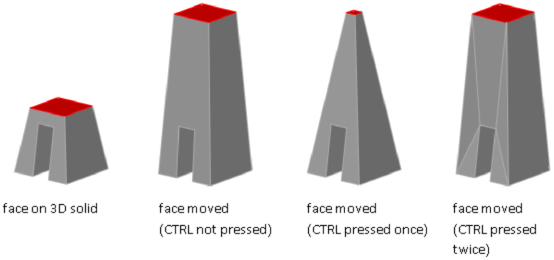
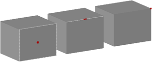
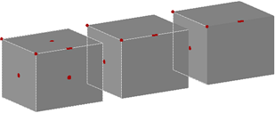
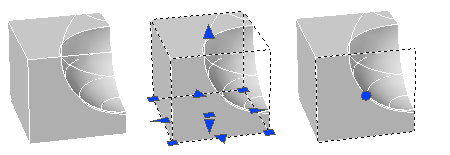
Several results are possible when you modify a solid. When you move, rotate, or scale subobjects, you can press Ctrl one or more times as you drag to cycle through modification options. The following illustration shows the modification options for moving a face.
Move, Rotate, and Scale Subobjects on Composite Solids – When you modify composite solids, the effect of the edits depends on the current setting of the History property.
- To modify subobjects of each history component separately, the History property must be set to Record.
- To modify subobjects of the combined composite solid as a whole, the History property must be set to None.
Rules and Limitations When Moving, Rotating, and Scaling Subobjects – You can only move, rotate, and scale subobjects on 3D solids if the operation maintains the integrity of the solid. The following rules and limitations apply to moving, rotating, and scaling subobjects
- When you use grips to modify subobjects, grips are not displayed on the subobjects that cannot be moved, rotated, or scaled.
- In most cases, you can move, rotate, and scale both planar and non-planar faces.
- You can only modify an edge that is a straight line and that has at least one planar adjacent face. The planes of the adjacent planar faces are adjusted to contain the modified edge.
- You cannot move, rotate, or scale edges (or their vertices) that are imprinted inside faces.
- You can only modify a vertex if it has at least one planar adjacent face. The planes of the adjacent planar faces are adjusted to contain the modified vertex.
- When you drag a subobject, the final result might be different than the preview displayed during the modification. This result occurs when the solid geometry is adjusted in order to maintain its topology. In some cases, the modification is not possible because it changes the topology of the solid too severely.
- If the modification causes spline surfaces to be extended, the operation is often unsuccessful.
- You cannot move, rotate, or scale non-manifold edges (edges that are shared by more than two faces) or non-manifold vertices. Also, if some non-manifold edges or vertices are present near faces, edges, and vertices that you modify, the operation might not be possible.
Move, Rotate, and Scale Faces on 3D Solids – Use the MOVE, ROTATE, and SCALE commands to modify faces just as you would with any other object. Press Ctrl+click to select a face on a solid. If you move, rotate, or scale a face on a 3D solid primitive, the solid primitive’s history is removed. The solid is no longer a true primitive and cannot be manipulated using grips or the Properties palette.
Move, Rotate, and Scale Edges – Move, rotate, and scale the edges on 3D solids using grips, gizmos, and commands.

You can use MOVE, ROTATE, and SCALE to modify edges on 3D solids just as you can for any other object. Press and hold Ctrl to select the edge. If you move, rotate, or scale an edge on a 3D solid primitive, the history of the solid primitive is removed. The solid is no longer a true primitive and cannot be manipulated using grips and the Properties palette. Edges on regions can be selected, but do not display grips. These edges can also be moved, rotated, and scaled.
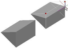
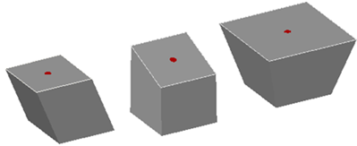
Modify Vertices on 3D Objects – Move, rotate, scale, or drag the vertices of 3D solids.
You can modify the form of a 3D solid by modifying one or more vertices. Use grips and gizmos, or run the MOVE, ROTATE, or SCALE command. When you scale or rotate vertices, you must select two or more vertices to see a change in the solid object. Clicking and dragging a vertex “stretches” the 3D object.
If you move, rotate, or scale one or more vertices on a 3D solid primitive, the solid primitive history is removed. The solid is no longer a true primitive and cannot be modified using grips and the Properties palette.
