An elevator (or lift) is a type of vertical transport equipment that efficiently moves people or goods between floors (levels, decks) of a building, vessel or other structures. Elevators are generally powered by electric motors that either drive traction cables or counterweight systems like a hoist, or pump hydraulic fluid to raise a cylindrical piston like a jack.
Elevator Types
According to hoist mechanism: Elevators will be classified according to hoist mechanism to 4 main types as follows:
- Hydraulic Elevators
- Traction Elevators
- Climbing elevator
- Pneumatic Elevators
According to building height:
- Low-Rise buildings (1- 3 stories) – Buildings up to about (1 to 3) stories typically use hydraulic elevators because of their lower initial cost
- Mid-Rise buildings (4 -11 stories) Buildings up to about (4 to 11) stories typically use Geared Traction Elevators
- High-Rise buildings (12 + stories) – Buildings up to about 12+ stories typically use Gear-Less Traction Elevators
According to building type: Elevators will be classified according to building type to 6 main types as follows:
- Hospital Elevators.
- Residential /Domestic Elevators.
- Agricultural Elevators.
- Industrial Elevators.
- Commercial Elevators.
- Parking buildings Elevators.
Elevator doors are normally opened by a power unit that is located on top of the elevator car. When an elevator car is level with a floor landing, the power unit moves the car door open or closed. A pick-up arm (clutch, vane, bayonet, or cam) contacts rollers on the hoistway door which releases the door latch on the hoistway door. The power unit opens the car door which in turn opens the hoistway door. The door rollers and pick-up arm may be different on various elevators but they all work on the same principle.
Elevator Components
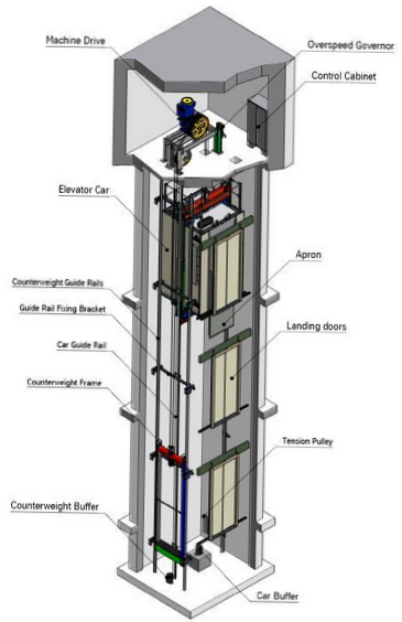
The standard elevators will include the following basic components:
Car – Elevator Car is the vehicle that travels between the different elevator stops carrying passengers and/or goods, it is usually A heavy steel frame surrounding a cage of metal and wood panels. Standard elevator car/cabin can be classified according to the number of entrances and their locations as
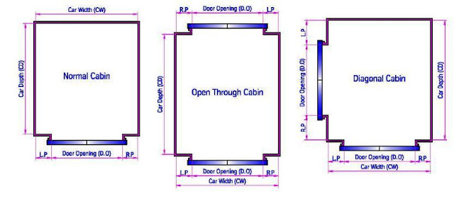
To prevent overloading of the car by persons, the available area of the car shall be limited and related to the nominal/rated load of the elevator. The number of passengers shall be obtained from the formula: Number of passengers = rated load /75, where 75 represent the average weight of a person in Kg. The value obtained for the number of passengers shall be rounded to the nearest whole number. The following definitions for the car dimension are very important
- Car Width (CW): The horizontal dimensions between the inner surfaces of the car walls measured parallel to the front entrance and at 1m above the car floor.
- Car Height (CH): The inside vertical distance between the entrance threshold and the constructional roof of the car. Light fittings and false ceilings are accommodated within this dimension.
- Car Depth (CD): The horizontal dimensions between the inner surfaces of the car walls measured at right angles to the car width and at 1m above the car floor.
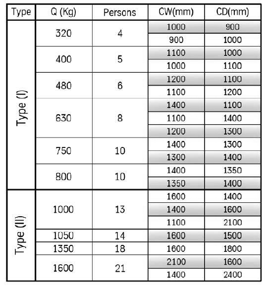
The following table shows the standard car sizes related to the elevator nominal loads.
Elevator Car is composed of the following components:
- Car Sling, a metal framework connected to the means of suspension,
- The elevator cabin
- Mechanical accessories, as Car door and door operator, Guide shoes and Door Protective Device.
Hoistway – Hoistway is the space enclosed by fireproof walls and elevator doors for the travel of one or more elevators, dumbwaiters or material lifts. It includes the pit and terminates at the underside of the overhead machinery space floor or grating or at the underside of the roof where the hoistway does not penetrate the roof. (Hoistway is sometimes called “hatchway” or “hatch”.)
A simple definition for the hoistway is the shaft that encompasses the elevator car. Generally the Hoistway serving all floors of the building but in high-rise buildings hoistways may be banked with specific hoistways serving only the lower floors and others serving only middle or upper floors while traveling in a blind hoistway until reaching the floors that it serves. A blind hoistway has no doors on the floors that it does not serve.
Hoistway is equipped with the following components:
- Guide rails for both the car and counterweight – Guide Rails are Steel Tracks in the form of a “T” that run the length of the hoistway, round, or formed sections with guiding surfaces to guide and direct the course of travel of an elevator car and elevator counterweights and Usually mounted to the sides of the hoistway.
- Counterweight – Counterweight is A tracked weight that is suspended from cables and moves within its own set of guide rails along the hoistway walls. Counterweight is used for balancing the mass of the complete car and a portion of rated load, and it will be equal to the dead weight of the car plus about 40% of the rated load. It also reduces the necessary consumed power for moving the elevator.
- Suspension (Hoisting) Ropes (Cables) – Suspension Ropes are Suspension means for car and counterweight, which are represented by steel wire ropes. They are Used on traction type elevators, usually attached to the crosshead and extending up into the machine room looping over the sheave on the motor and then down to the counter weights. Hoisting cable are generally 3 to 6 in number. These ropes are usually 1/2”or 5/8” in diameter.
- Landing (Hoistway) doors – The door that is seen from each floor of a building is referred to as the outer or hoistway door. This hoistway door is a part of the building (each landing). It is important to realize that the car door does all the work; the hoistway door is a dependent. These doors can be opened or closed by electric motors, or manually for emergency incidents. Safety devices are located at each landing to prevent inadvertent hoistway door openings and to prevent an elevator car from moving unless a door is in a locked position. The difference between the car doors and the hoistway doors is that the elevator car door travels through the hoistway with the car but the hoistway doors are fixed doors in each landing floor.
- Buffers in the pit – A Buffer is a device designed to stop a descending car or counterweight beyond its normal limit and to soften the force with which the elevator runs into the pit during an emergency. They may be of polyurethane or oil type in respect of the rated speed.
Machine/drive system – Driving machine, this is the power unit of the elevator, and usually located at the elevator machine room. The Driving machine used to refer to the collection of components that raise or lower the elevator. These include the drive motor, brake, speed reduction unit, sheaves and encoders.
Types of Driving Machines: Generally, there are three standard types of driving machines provided for elevators. These are;
- Gearless Machine – It used in high rise applications whereby the drive motor and drive sheave are connected in line on a common shaft, without any mechanical speed reduction unit located between the drive motor and drive sheave. Generally, Gearless machines are used for high speed lifts between 2.5 m/s to 10 m/s and they can be also used for lower speeds for special applications. Their sizes and shapes vary with load, speed and manufacture but the underlying principles and components are the same.
- Geared Machine – It used in low and midrise applications. This design utilizes a mechanical speed reduction gear set to reduce the rpm of the drive motor (input speed) to suit the required speed of the drive sheave and elevator (output speed). Generally, geared machines are used for speeds between 0.1 m/s and 2.5 m/s and are suitable for loads from 5 Kg up to 50,000 Kg and above. Their sizes and shapes vary with load, speed and manufacture but the underlying principles and components are the same.
- Drum Machine – It widely used in older passenger and freight elevator applications, though now rarely seen except for dumbwaiters. For many years now the Elevator Safety Code has disallowed the use of such machines for passenger applications. A drum design has one end of the suspension rope affixed to the inside of the winding drum’s drive sheave, and then allows to rope to reel in or off the outer surface of its sheave, depending upon the car direction of travel.
Elevator Machine Room is Enclosure in which the machinery and electrical controls used for an elevator are contained. The room must be fully enclosed or otherwise secured against non-authorized access. Usually located above the hoistway in a penthouse or two floors above the highest floor it serves, but may be in the basement if overhead space is unavailable.
Main Components of machine drive system:
- Electrical Motor: Electrical Motor is used to raise and lower the elevator cab, the direction of motor rotation and speed (revolutions per minute) are directed and supervised by devices located within the elevator controller, The motor component of the elevator machine can be either a DC motor or an AC motor
- Traction (Drive) Sheave: The powered pulley connected to either the elevator drive motor’s output shaft (gearless) or to the output side of the mechanical speed reduction unit (geared). The circumference of the sheave has a series of “U” or “V” shaped grooves cut into it (as shown in below image), in which sit the elevator suspension or hoist ropes. The friction loads created as the suspension ropes pass over the grooved surface of the sheave causes motion to be transmitted from the drive motor to the elevator cab or counterweight.
- Secondary Sheave: Pulley that is normally used on gearless elevators and is located directly beneath the machine or drive sheave. It too has a grooved surface over which pass the suspension or hoist ropes.
- Deflector Sheave: Pulley used to offset or direct the vertical drop or location of the steel hoist ropes running between the elevator car and its counterweight. Where the horizontal distance between the hitch point for the car and the counterweight is larger than the diameter of the drive sheave, one or more deflector sheaves are used to guide the hoist ropes. These devices are grooved sheaves that lead elevator suspension ropes off the drive sheave down to the car top and counterweight. The number and size of deflector sheaves will be a function of the elevator’s size, machine placement and roping arrangement.
- Brake: Traction and drum machines are provided with a mechanical brake, designed to stop and safely hold an elevator. A centrifugal force governor is provided on most elevators to guard against over speeding (when a car travels in excess of 20% of top speed, the governor will activate a safety stop device). Safeties are installed at the bottom of an elevator car and occasionally on counterweights to provide positive emergency stopping when activated by the governor.
- Speed reduction unit or gearbox – The most common type of speed reduction unit consists of a hardened steel worm shaft, mated with a bronze ring or crown gear (worm-gear set). The mating surfaces of these two elements are contained within an oil bath for lubrication. Regular access to the machine to check the level of oil, as well as the condition of the oil and the ring gear is an important aspect of ongoing equipment maintenance.
Safety System – The following list describes all the safety components used in electrical traction elevator safety system:
- Device for locking landing doors (Hoistway Door Interlock)
- Progressive safety gear
- Over speed governor
- Buffers
- Final Limit switches
- Other safety devices and switches
Device for locking landing doors (Hoistway Door Interlock) – It shall not be possible in normal operation to open the landing door (or any of the panels in the case of a multi-panel door) unless the car has stopped, or is on the point of stopping, in the unlocking zone of the door. The unlocking zone shall not extend more than 0.2 meter above and below the landing level. The hoistway door locking mechanism provides a means to mechanically lock each hoistway door and the elevator cannot leave a landing unless the doors are fully closed and secured.
They are also interconnected electrically to prevent operation of the elevator if any of the elevator’s hoistway doors are open. Should the doors be forced open, the interlock circuit will be broken, causing the elevator to immediately stop. Each landing door shall be provided with a locking device satisfying the previous conditions. This device shall be protected against deliberate misuse. Landing doors shall be capable of being unlocked from the outside with the aid of key , which fit the unlocking triangle (Hoistway Emergency Door Keys).
Progressive safety gear – Safety gear is a mechanical device for stopping the car (or counterweight) by gripping the guide rails in the event of car speed attaining a pre-determined value in a downward direction of travel, irrespective what the reason for the increase in speed may be.
Progressive safety gear retardation is affected by a breaking action on the guide rails and for which special provisions are made so as to limit the forces on the car, counterweight of balancing weight to a permissible value. Pair of safety gears is mounted in the lower part of car sling and operated simultaneously by a linkage mechanism that actuated by over speed governor.
Dependent on the direction the safety lever is pulled upwards or downwards; the movement of the lever is transmitted to the shearing mechanism by means of a rocker. The grip wedges of progressive safety gear or braking device which are linked with the safety-gear levers are released from their rest position between rail and jaw body which is maintained by a spring assembly. The safety-gear lever assembly which is arranged in the form of a shearing mechanism ensures that the progressive safety gears and/or braking device are activated simultaneously and in pairs.
The progressive safety gear and the braking device are reset by moving the car opposite to direction of safety gear operation. (Move car in electric recall mode, or if necessary, by releasing the car from the engaged position).
Safety switch is mounted on the bottom transom on the side of the safety-gear. The switch is operated by the movement of the safety-gear lever up or down according to actuation direction if the car travels at over speed. The switch interrupts the safety circuit causing machine drive power off.
Over speed governor – Over speed governor function is to actuate the safety gear if the car speed exceeds 115% of its rated value. Usually a cable is attached to the safeties on the underside of the car, called the governor rope. This rope runs down through a pulley at the bottom of th shaft and back up to the machine room and around the governor sheave.
When over-speeding is detected, the governor grips the cable which applies the safeties that wedge against the guide rails and stops the car. The over speed governor works on the floating principle with a cam curve and roller guided rocker. It is situated either in the machine room or in the head room. Over speed governer is provided by a factory adjusted switch activated when the tripped speed is reached to disconnect the achine drive starting with governor pulley blocking.
Buffers – A Buffer is a device designed to stop a descending car or counterweight beyond its normal limit and to soften the force with which the elevator runs into the pit during an emergency. They may be of polyurethane or oil type in respect of the rated speed. There are two principal types of buffers in existence
- Energy accumulation: accumulate the kinetic energy of the car or counterweight.
- Energy dissipation: dissipate the kinetic energy of the car or counterweight.
Final Limit Switches – Final limit switches shall be set to function as close as possible to the terminal floors (the highest or lowest landing of lifts), without risk of accident. Final limit switches shall operate before the car comes into contact with the buffers. The action of the final limit switches shall be maintained whilst the buffers are compressed.
After the operation of final limit switches, the return to service of the lift cannot occur automatically.
Other Safety Devices and Switches
- Overload Device – Load weighing device or the overload sensor is mounted on the lower transom to sense the nearness of car floor during loading of isolation springs. The sensor is operated by altering the distance between car floor and sling dependent on the load. A distance screw shall be provided close to the sensor for protection purposes. Set the distance screw in such a way that it projects the sensor by an approximately 1 mm, so that the sensor is protected in the case of shock motions which raise during safety gear operation of the car.
- Door Protective Device – any type of device used with automatic power operated doors that detect obstructions to the normal closing of the elevator doors (though contact may occur) and either causes the doors to change the door motion by either stopping it, or causing it to reverse (reopen) or go into some other mode of operation, such as nudging. A safe edge, a safety astragal, a photoelectric device (safe ray), and electrostatic field device are examples of door protective devices.
- Emergency stop switch – The red switch inside some cars that cuts off the power to the car except for the lights, alarm and communication system.
- Emergency Alarm Switch – It will sound an alarm when activated by a passenger and in most elevators; an emergency telephone or intercom can serve as a link to assistance if the car should stall.
Control System – Elevator Control System is the system responsible for coordinating all aspects of elevator service such as travel, speed, and accelerating, decelerating, door opening speed and delay, leveling and hall lantern signals. It accepts inputs (e.g. button signals) and produces outputs (elevator cars moving, doors opening, etc.). There are 3 main types for elevator control systems as follows:
- Single Automatic operation: First automated system w/o single call button on each floor and single button for each floor inside car. Called if no one is using it. Passenger has exclusive use of the car until rip is complete.
- Selective collective operation: Most common, remembers and answers calls in one direction then reverses. When trip complete, programmed to return to a home landing.
- Group automatic operation: For large buildings with many elevators which are controlled with programmable microprocessors to respond.
The elevator as a control system has a number of components. These can basically be divided into inputs, outputs and controllers.
Inputs, which include:
- Sensors – For magnetic sensor, these pick up signals regarding the location of the car. This sensor is usually placed on the car itself and reads the position by counting the number of holes in the guide rail as they pass by in the photo-electric sensor or in the case of the magnetic sensor, the number of magnetic pulses. For infrared, is used to detect people entering or leaving the elevator. Weight sensor is placed on the car to warn the control system if the design load is exceeded.
- Buttons – Hall Buttons are on a button panel on the outside of the elevator shafts and are used by potential passengers to call an elevator cab to the floor that the pressed summon button is located on. There are two Hall buttons on each floor – one for up, another for down, except on the top floor where there is only down and on the bottom floor where there is only up. The controller interacts with these buttons by receiving press and release signals indicating the requested direction and floor number. It also sends light on/off signals to indicate the status of the buttons. Floor Request Buttons are located on a button panel on the interior of each elevator cab. The controller interacts with these buttons by receiving pressed signals indicating the desired floor number and elevator cab which they were pressed from. It also sends light on/off signals to indicate the status of the buttons. Open Door Button is on the interior button panel of each cab. A passenger can press this button to open the elevator doors or keep pressing it to keep them open, but only when the elevator cab is stopped at a floor. Some elevator systems also have a close door button, but this one does not. The controller interacts with this button by receiving a signal when it is pressed and when it is released. Both of these signals include the cab from which they came from. Emergency Stop Button is on the interior button panel of each cab. A passenger can press this button to stop the elevator no matter where it is in a shaft. The controller interacts with this button by receiving a signal from it that indicates that it was pressed, as well as the cab that it came from. Emergency Bell Button is on the interior button panel of each cab. A passenger can press this button to sound a bell to alert people outside of the elevator shaft that someone is trapped inside the elevator cab in case of a malfunction. The controller interacts with this button by receiving a signal from it that indicates that it was pressed.
- Key controls – Key controls may only be activated by the proper keys, and their use is thus restricted to repair people, elevator operators or firemen. It is used in place of or in conjunction with a pushbutton to restrict access to a floor. Keypads and card readers are also available.
- System controls – System controls are used to turn the elevator system on or off, system controls are only accessible from an elevator control room. They would typically be used quite infrequently – perhaps the system would be turned on early in the morning and turned off late at night, or turned off at the start of holidays and turned on once the next term begins.
Outputs, which include:
- Actuators – On top of each elevator cab is a door opening device. This device opens the inner door of the elevator cab and the outer door of the elevator shaft simultaneously at each floor. The controller interacts with the door opening device by sending signals to open or close the doors and by receiving signals when the doors have been completely opened or closed. The signals that the controller receives also indicate which cab they are coming from.
- Bells – Emergency Bell is used to alert people outside of the elevator system that someone is trapped inside an elevator cab. The controller interacts with the emergency bell by sending it a signal to ring. Load Bell is used to alert the passengers inside the cab that there is too much weight in it to operate it safely. The controller interacts with the load bell be sending it a signal to ring.
- Displays – Car Position Display indicates to its passengers which floor the elevator cab is currently on. Some elevator systems have this floor number display on every floor outside of the elevator doors, but this system does not. The controller interacts with this display by sending a signal that tells it which floor number to display. Can be either analog (individual indicators for each floor) or digital ( a dot matrix or segmented LED that changes to indicate the floor level). Direction Display indicates the current direction of an elevator cab; it is either up or down. The controller interacts with this display by sending it a signal that tells it which direction to display.
Controller – The controller is a device which manages the visual monitoring, interactive command control and traffic analysis system to ensure the elevators are functioning efficiently. The primary function of the elevator controller is essentially to receive and process a variety of signals from several different components of a whole elevator system. It is able to send signals in response to the ones it receives in order to operate all of the other components in the system. This exchange of signals is how the elevator controller is able to keep the elevators running smoothly on a day-to-day basis.
Here are a few of the following ways the controller interacts with the other components of the elevator system:
- Controls the speed of elevator engines in order to move elevator cabs up and down their respective shafts.
- Queues and processes elevator summons and floor requests from passengers through the signals provided to it by several buttons.
- Processes information sent to it by load sensors in order to ensure that the load of a cab never exceeds the safety limit.
- Processes information sent to it by position marker sensors in order to keep track of where the elevator cabs are at all times, as well as their speed.
- Provides feedback to passengers through the lights on some of the buttons and the floor number and direction displays in each cab.
- Can sound alarm bells that are either invoked by trapped passengers or required to warn of excess load in a cab.
- Controls the operation of the elevator doors of a cab through communication with door opening devices.
There are 3 primary types of controller technology used to process the logic of the controller as follows:
- Relay based controller (electromechanical switching) – A relay is a very dependable device consisting of an electromagnet that opens and closes contacts, routing the logic to various circuits. A simple elevator with a few stops and manual door operation can be served well by a relay controller. Relays can also be used for more complex elevators, and in fact were until the 1980’s. However, the number of relays required can make it difficult to troubleshoot should there ever be a problem.
- Solid-State Logic Technology – It includes both discreet transistors circuits and integrated circuit boards. It gives improved reliability, lower power consumption and easy fault diagnosis than electromagnetic relay technology.
- PLC controller (computer based technology) – The advent of personal computers has made microprocessor technology affordable for many other fields. Elevator Concepts utilizes a special type of industrial computer called a Programmable Logic Controller PLC to control the logic of more complex jobs. They are very dependable, compact, and simple to troubleshoot.
Elevator Maintenance
An elevator is an extremely complex system with hundreds of parts that must be maintained. One function of maintenance is ensuring continued operation by preventing excessive wear and breakdown. In systems as complex as modern elevator systems, a more important aspect of maintenance is to ensure that the equipment continues to perform as it was originally designed. This can be accomplished only by qualified, trained technicians using the correct equipment and tools.
Inside the Car:
- Examine the interior of the elevator car for damage to the walls, ceiling, and handrails.
- Examine the position indicator lights and replace any burned out lights.
- Operate the elevator going up and down and check the leveling accuracy, acceleration, and deceleration. Make any adjustments deemed necessary.
- Check to make sure that the door moves smoothly and does not slam or bounce.
- Make sure the door restrictor operates properly and make any necessary repairs.
Outside the Car
- Check the hall stations and lights and replace any burned out lights.
- Inspect the door panel and clearances.
- Test the Phase 1 firefighters’ service.
Machine Room
- Make sure the machine room does not contain any material unrelated to the elevator.
- Check components for leaks, unusual vibration, or wear.
- Inspect electrical components for evidence of overheating or failure.
- Lubricate components, if necessary.
- Check the oil level.
- Make any necessary adjustments or schedule follow-up service.
Top of Car
- Check that the stop switch and inspection station function properly.
- Remove any debris from the top of the car.
- Inspect any visible components, including rollers, guide rails, and leveling devices.
- Check the traveling cables for wear and inspect connections.
- Inspect the door operator and its components.
- Check the hoistway for evidence of rodents, fire safety, and vandalism.
Pit
- Make sure that the stop switch, lights, and GFI outlet function properly.
- Clean the pit and check for signs of leaks.
- Inspect the spring buffers for signs of corrosion, alignment, and secure attachment.
- Inspect all visible components, including rollers, guide rails, safeties, and switches.
- Check the travel cable for wear, pinches, and snags.
- Make sure the sump pump is clean and operating correctly.
Elevator Machine Room
The elevator machine room is the heart of the elevator system. It contains the elevator hoisting machines, motor generator sets or solid-state power supply, and control equipment. The control equipment is an essential part of the total operating mechanism that accelerates, decelerates, and levels the car at each floor. Most of the routine maintenance takes place in the machine room. This includes routine servicing of motors, generators, switches, contacts, brakes, and controls.
Hoistway
The hoistway contains the guide rails on which the elevator car and counterweight run; the corridor doors, hangers, door locks, and operating mechanisms; switches and other operating and safety devices; and space for cables and other equipment. Equipment within hoistways that requires maintenance includes buffers, corridor door hangers and locks, switches, and safety devices. Most maintenance of these components must be performed from inside the hoistway and outside the elevator car. The hoistway pit houses the car and counterweights buffers, cable pulley and tensioning devices, and limit switches. The overhead of the hoistway may contain the over speed governor mechanism and limit switches with space for the safety of personnel on the top of the elevator car.
The hoistway is a dangerous place to work. For safety, only qualified personnel should perform elevator maintenance and repair work.
Rotine Elevator Maintenance Checklist
To antain proper elevator operation, check and correct:Response time
- ravel time between floors
- Leveling
- Door operation
- Starting and stopping
- Hall and call lights and floor indicators
Tmaintain elevator support systems, check and repair:
- Emergency lighting and alarms
- Communications devices (for example, intercoms or telephones)
- To maintain the physical condition of an elevator:
- Maintain cleanliness
- Check for and repair interior damage
- Check signage and repair when necessary
Elevator Performance Review
Elevator performance and maintenance go hand in hand. Poor maintenance or performance is indicated by increased floor-to-floor elevator operating and/or waiting times. Periodically, the property manager should time elevator functions and compare them with the manufacturer’s specifications in order to evaluate the overall system performance.
Check elevator performance by riding the elevators. Concentrate on sounds by alternately closing your eyes and covering your ears to intensify what you see, hear, and feel. Listen to the comments of people using the elevators.
Operations that are commonly timed and checked include the followingFloor-to-floor time: Time required to make a one-floor run. Measured from the time the hoistway doors start to close at one floor until they are fully open at the next floor.
- Performance time: Measured from the time the doors start to close at one floor until they are sufficiently open to allow passenger exchange at the next floor.
- Car start time: Measured from the time the doors start to close until the elevator actually moves.
- Brake-to-brake time: Measured from the time the car starts until it stops on a one-floor run.
- Door open time: Measured from the time doors start to open until fully open.Door dwell time: Length of time doors remain fully open by car or hall call without being affected by cancellation features.
The above tests should be performed near a mid-floor stop. Measurements should be taken in both directions and averaged.
