Electric motors defined as electromechanical devices that convert electrical energy to mechanical energy; they are the interface between the electrical and mechanical systems of a facility. Electric motors are an important part of any electrical system. They used throughout every manufacturing plant, office, and home consuming about 64% of all electricity generated. There are numerous ways to design a motor, thus there are many different types of motors and each type possess different operating characteristics (that will be listed later). Based on these characteristics the motor can be chosen for a specified application.
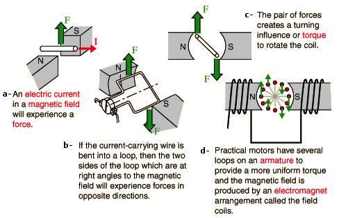
Electrical current flowing in a loop of wire will produce a magnetic field across the loop. When this loop is surrounded by the field of another magnet, the loop will turn, producing a force (called torque) that results in mechanical motion
Electric machines are classified into two categories D.C. and A.C. motors. The basic parts for AC motors are as follows:
- Enclosure – A motor’s enclosure not only holds the motor’s components together, it also protects the internal components from moisture and containments. The degree of protection depends on the enclosure type.
- Stator – The stator is the stationary part of the motor’s electromagnetic circuit. The stator is electrical circuit that performs as electromagnet. The stator core is made up of many thin metal sheets, called laminations. Laminations are used to reduce energy losses that would result if a solid core were used.
- Stator laminations are stacked together forming a hollow cylinder. Coils of insulated wire are inserted into slots of the stator core.
- When the assembled motor is in operation, the stator windings are connected directly to the power source. Each grouping of coils, together with the steel core it surrounds, becomes an electromagnet when current is applied. Electromagnetism is the basic principle behind motor operation.
- Rotor – The rotor is the rotating part of the motor’s electromagnetic circuit. Magnetic field from the stator induces an opposing magnetic field onto the rotor causing the rotor to “push” away from the stator field.
- Bearings – Bearings, mounted on the shaft, support the rotor and allow it to turn. Not all bearings are suitable for every application; a universal, all-purpose bearing does not exist.
- Conduit Box – Point of connection of electrical power to the motor’s stator windings.
- Eye Bolt – Used to lift heavy motors with a hoist or crane to prevent motor damage.
The basic parts for DC motors are as follows:
- Stator – The stator carries the field winding and Poles. The stator together with the rotor constitutes the magnetic circuit or core of the machine. It is a hollow cylinder.
- Rotor – It carries the armature winding. The armature is the load carrying member. The rotor is cylindrical in shape.
- Armature Winding – This winding rotates in the magnetic field set up at the stationary winding (Field winding). It is the load carrying member mounted on the rotor. An armature winding is a continuous winding; that is, it has no beginning or end. It is composed of a number of coils in series.
- Field Winding – This is an exciting system which may be an electrical winding or a permanent magnet and which is located on the stator. DC Motors are generally classified by how their Armature & Field windings are connected to their DC power supply.
- Commutator – The coils on the armature are terminated and interconnected through the commutator which comprised of a number of bars or commutator segments which are insulated from each other. The commutator rotates with the rotor and serves to rectify the induced voltage and the current in the armature both of which are A.C.
- Brushes – These are conducting carbon graphite spring loaded to ride on the commutator and act as interface between the external circuit and the armature winding.
- Poles – The field winding is placed in poles, the number of which is determined by the voltage and current ratings of the machine.
- Slot/Teeth – For mechanical support, protection from abrasion, and further electrical insulation, non-conducting slot liners are often wedged between the coils and the slot walls. The magnetic material between the slots is called teeth.
- Motor Housing – The motor housing supports the iron core, the brushes and the bearings.
Motor Maintenance
The ideal motor maintenance program aims at preventing breakdowns rather than repairing them. Systematic and periodic inspections of motors are necessary to ensure best operating results. In a good preventive maintenance program with detailed checks, the person in charge should have a record card on file for every motor in the plant. Entries on the card should include inspection dates, descriptions of repairs, and the costs involved. When the record indicates that a motor has undergone excessive and /or costly repairs, the causes can be determined and corrected.
Inspection records also serve as a guide to indicate when motors should be replaced because of their high cost of operation. They also reveal faulty operating conditions, such as misapplication or poor drive engineering.
Inspection and servicing should be systematic. However, the frequency of inspections and the degree of thoroughness may vary, as determined by the plant maintenance engineer. Such determinations are based on 1) the importance of the motor in the production scheme (if the motor fails, will production be slowed seriously, or stopped?), 2) the percentage of the day the motor operates, 3) the nature of the service, and 4) the motor’s environment. An inspection schedule, therefore, must be flexible, and adapted to the needs of each plant. Equipment manufacturers’ specifications and procedures should be consulted and followed.
The following schedule, which covers both ac and dc motors, is based on average conditions insofar as operational use and cleanliness are concerned. (Where dust and dirty conditions are extremely severe, open motors may require a certain amount of cleaning every day.)
Every week
- Examine commutator and brushes, ac and dc.
- Check oil level in bearings.
- See that oil rings turn with shaft.
- See that exposed shaft is free of oil and grease from bearings.
- Examine the starter switch, fuses, and other controls; tighten loose connections.
- See that the motor is brought up to speed in normal time.
Every six months
- Clean motor thoroughly, blowing out dirt from windings, and wipe commutator and brushes.
- Inspect commutator clamping ring.
- Check brushes and replace any that are more than half worn.
- Examine brush holders, and clean them if dirty. Make certain that brushes ride free in the holders.
- Check brush pressure.
- Check brush position.
- Drain, wash out, and replace oil in sleeve bearings.
- Check grease in ball or roller bearings.
- Check operating speed or speeds.
- See that end play of shaft is normal.
- Inspect and tighten connections on motor and control.
- Check current input and compare it with normal.
- Examine drive, critically, for smooth running, absence of vibration, and worn gears, chains, or belts.
- Check motor foot bolts, end-shield bolts, pulley, coupling, gear and journal set screws, and keys.
- See that all covers, and belt and gear guards are in place, in good order, and securely fastened.
Once a year
- Clean out and renew grease in ball or roller bearing housings.
- Test insulation by megohmmeter.
- Check air gap.
- Clean out magnetic dirt that may be clinging to poles.
- Check clearance between shaft and journal boxes of sleeve bearing motors to pre vent operation with worn bearings.
- Clean out undercut slots in commutator. Check the commutator for smoothness.
- Examine connections of commutator and armature coils.
- Inspect armature bands.
Here are some guidelines that you can use for effective maintenance
Lubrication. Lubricate regularly according to manufacturer’s instructions. On sleeve-bearing and other oil-lubricated machines, check oil reservoirs on a regular basis. In poor environments, change oil at least once a month. Never over-lubricate; excess grease or oil can get into windings and deteriorate insulation. Be sure to use only the lubricant specified for the machine in question. However, you should also check into the possibility of using modern lubricants that have excellent life and lubricating qualities.
Bearing inspection. Bearing failures are one of the most common causes of motor failures. Typical bearing problems include improper lubrication, misalignment of the motor with the load, replacement with the wrong type bearing, excessive loading, and harsh environments.
On essential motors or those that are heavily used or frequently duty cycled, you should check bearings daily using a stethoscope or infrared scanner (or camera, if appropriate). Check bearing surface temperature with a thermometer, electronic temperature sensing devices, or stick-on temperature indicating labels. Compare temperature of hot bearings with the temperatures of normally operating bearings. Check oil rings and watch for excessive end play.
Rotor/stator inspection. Check air gap between the rotor and stator with feeler gages at least annually. Measurements should be made at the top, bottom, and on both sides of the stator. Differences in readings obtained from year to year indicate bearing wear.
Belt inspection. Check belt tension; belts should have about 1 in. of play. Sheaves should be seated firmly with little or no play. Couplings should be tight, within tolerances, and should operate without excessive noise. An alignment check should be made on all motor-generator sets and on motor-load couplings when trouble is suspected.
Brush/commutator inspection. Inspect brushes and commutators of DC motors for excessive wear. Check brushes for proper type, hardness, conductivity, and fit in brush holders. Check holder spring pressure with a small scale. In most instances, pressure should be 2 to 2 1/2 lbs per sq in. of brush cross-sectional area. Call manufacturer or service company to solve recurring problems of brush chatter, excessive brush wear, and sparking, streaking, or threading of commutator.
Motor mount inspection. Check mounting bolts, steel base plates for possible warping, and concrete base for cracking or spalling.
Annually, perform vibration-analysis tests. Excessive vibration may be hard to detect by hand, but it could be enough to shorten motor life significantly. It can cause bearing failure, metal fatigue of parts, or failure of windings. The cause of vibration is usually mechanical in nature, such as excessive belt tension, defective sleeve or ball bearings, misalignment, or improper balance. The most common cause is the unbalance of a rotating member (the motor rotor, rotating load, or other drive train component). Simple testing of the motor is done by uncoupling the load or removing the belts and then running the motor. Electrical problems also can cause vibration.
Field vibration analysis can be accomplished by using a portable instrument that identifies vibrations and displays their amplitudes and frequencies.
Motor temperature control. Restricted ventilation will cause a motor to operate at a higher than desired temperature. Dirt, dust, chemicals, snow, oil, grass, weeds, etc., can clog ventilation passages of an open-frame motor. Keep motor clean and cool. In poor environments, blow out dirt with dry compressed air (no more than 50 lbs) as often as needed.
Open drip proof and totally enclosed motors are protected but must not be installed where air flow will be restricted or where excessive ambient temperatures might be encountered. In high-temperature locations, consider the use of energy-efficient motors that operate cooler than standard motors. Excessive ambient temperatures will shorten motor life.
Pull and disassemble important motors during summer shutdowns for thorough inspection, testing, cleaning, checking of bearings, couplings or accessories, or complete reconditioning.
Record keeping. Keep accurate records. Perform annual insulation-resistance (IR) and other appropriate tests. Important motors should also receive a thorough visual inspection, as well as voltage and current checks. All values should be recorded and compared each year. The trend of the readings will indicate the condition of the motor and offer a guide to its reliability.
Basic guidelines to control maintenance
These guidelines will help you maintain motor controls.
- In poor environments, blow out dirt weekly; in normal environments, a quarterly or semi-annual cleaning should be adequate. Make sure that dust or contamination is kept off high-voltage equipment. This is important because dust may contain conducting materials that could form unwanted circuit paths, resulting in current leakage or possible grounds or short circuits.
- Moving parts inspection. Moving parts should operate easily without excessive friction. Check operation of contactors and relays by hand, feeling for any binding or sticking. Look for loose pins, bolts, or bearings. If the control is dirty, it should be wiped or blown clean.
- Contact inspection. Check contacts for pitting and signs of overheating, such as discoloration of metal, charred insulation, or odor. Be sure contact pressure is adequate and the same on all poles; verify with manufacturer’s specification. Watch for frayed flexible leads.
Contact resistance testing. On essential controls, perform contact-resistance tests with a low-resistance ohmmeter on a regular basis. Proper contact resistance should be about 50 micro-ohms. Record readings for future comparison. This will indicate trends in the condition of contacts.
