Electric utilities transmit power from the power plant most efficiently at very high voltages. In the United States, power companies provide electricity to medium or large buildings at 13,800 volts (13.8kV). For small commercial buildings or residential customers, power companies lower the voltage with a transformer on a power pole or mounted on the ground. From there, the electricity is fed through a meter and into the building.
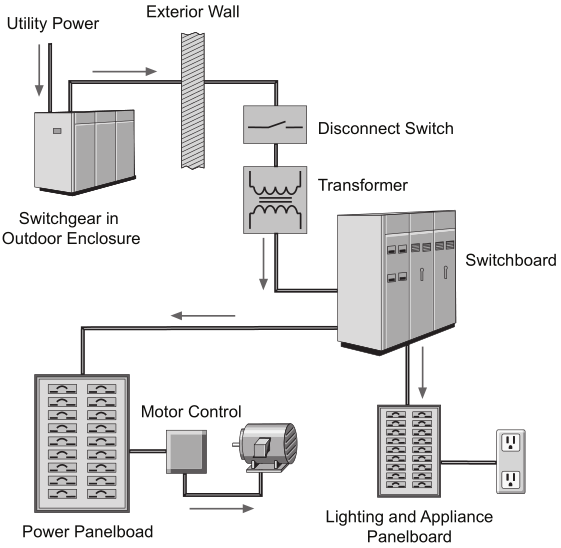
Power distribution systems used in multi-family, commercial, and industrial facilities are more complex. A power distribution system consists of metering devices to measure power consumption, main and branch disconnects, protective devices, switching devices to start and stop power flow, conductors, and transformers. Power may be distributed through various switchboards, transformers, and panelboards.
Power Distribution in Small Buildings
Small commercial or residential buildings have a very simple power distribution system. The utility will own the transformer, which will sit on a pad outside the building or will be attached to a utility pole. The transformer reduces the voltage from 13.8kV down to 120/240 or 120/208 volts and then passes the electricity to a meter, which is owned by the utility and keeps a record of power consumption.
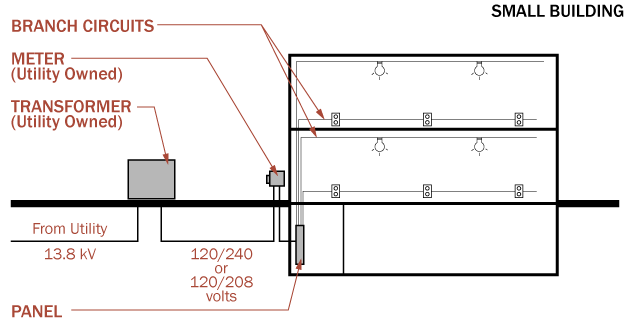
After leaving the meter, the power is transmitted into the building at which point all wiring, panels, and devices are the property of the building owner. Wires transfer the electricity from the meter to a panel board, which is generally located in the basement or garage of a house. In small commercial buildings, the panel may be located in a utility closet. The panel board will have a main service breaker and a series of circuit breakers, which control the flow of power to various circuits in the building. Each branch circuit will serve a device (some appliances require heavy loads) or a number of devices like convenience outlets or lights.
Power Distribution in Large Buildings
Large buildings have a much higher electrical load than small buildings; therefore, the electrical equipment must be larger and more robust. Large building owners will also purchase electricity at high voltages (in the US, 13.8kV) because it comes at a cheaper rate. In this case, the owner will provide and maintain their own step-down transformer, which lowers the voltage to a more usable level (in the US, 480/277 volts). This transformer can be mounted on a pad outside the building or in a transformer room inside the building.
The electricity is then transmitted to switchgear. The role of the switchgear is to distribute electricity safely and efficiently to the various electrical closets throughout the building. The equipment has numerous safety features including circuit breakers, which allow power to be disrupted downstream – this may occur due to a fault or problem, but it can also be done intentionally to allow technicians to work on specific branches of the power system.
It should be noted that very large buildings or buildings with complex electrical systems may have multiple transformers, which may feed multiple pieces of switchgear. We are keeping this article simple by sharing the basic concepts.
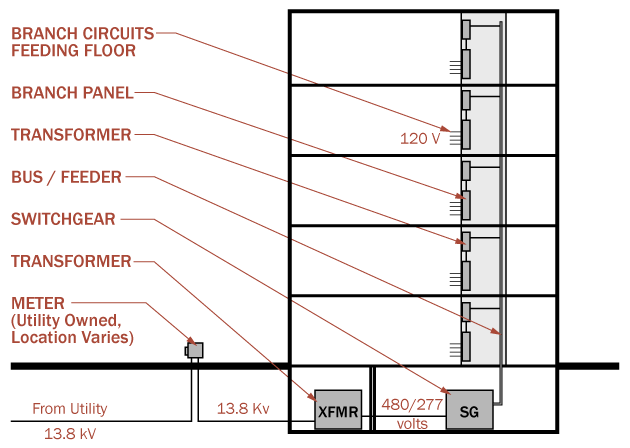
The electricity will leave the switchgear and travel along a primary feeder or bus. The bus or feeder is a heavy gauge conductor that is capable of carrying high amperage current throughout a building safely and efficiently. The bus or feeder is tapped as needed and a conductor is run to an electric closet, which serves a zone or floor of a building.
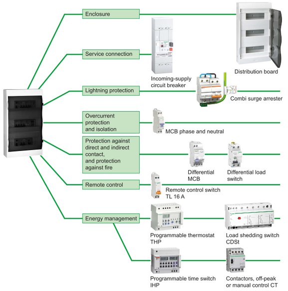
Distribution Board
A distribution board (also known as panelboard, breaker panel, or electric panel) is a component of an electricity supply system that divides an electrical power feed into subsidiary circuits, while providing a protective fuse or circuit breaker for each circuit in a common enclosure.
The distribution board system is most commonly adopted for distributing electrical energy in a building. Distribution board is normally in form of a kiosk, consists of number of fuse units for various circuits along with copper or aluminium bus bars for connecting two or more numbers of circuits across the main supply terminals. In simplest form of distribution board, there to copper or aluminium bus bar strips, fixed on the inner back wall of the metal kiosk with suitable insulator supports. One of the bus bar strips is connected with phase terminal and other bus bar strip is connected with the neutral terminal of the supply mains, via an isolation switch. There are numbers of fuse units generally placed parallelly, connected to the phase bus bar. Each of these fuse units feeds its own circuit. The return path or neutral of each circuit is normally connected directly to the neutral bus bar. All the loads are essentially connected parallelly across the distribution circuit. It should be noted that the cable feeding the distribution board must be capable enough to carry the maximum peak load current. There is no limitation of numbers of circuits connected to a distribution board but it is always preferable to employ sub distribution boards in case of larger distribution network in a multi-storage big building. Here each sub distribution board are connected to main distribution board through a link switch just as distribution circuit are connected to a distribution board. Normally main distribution board is installed near the supply mains whereas sub distribution boards are installed near the loads.
The tree system of electrical distribution is simplest and oldest form of electrical wiring system in a building. Here, main branch of electrical distribution is directly taken from supply mains through a link switch in series with a fuse unit. Each sub branch is taken from this main distribution branch through a fuse unit inserted in each of the sub branches. This is absolute type of electrical wiring system, not used in modern age because the voltages at all load terminals are not uniform and number of joints involved in these systems is quite large and also the fuse units are installed in scattered way in different points of the wiring. Another disadvantage of this system is, in case of occurrence of fault all the joints have to be opened and its some of these joints are concealed beneath floor or roof spaces, a lot of difficulties are faced. Some times in number of such joints are required to be opened for testing purpose, so damage is caused to installation, conductor and building too.
In joint box or tee system, an electrical load is connected through a joint box. In this method the phase and neutral connection for a load are taken out from the phase and neutral line of the system by means of tee connectors. These tee connections are made in a joint box. In this system for each connected load there is a tee connection in main phase wire and neutral wire. Due to absence of loop from one load to another, there is a great savings of electrical wire but at the same time because of joint boxes there is an extra cost involved in the system but still this system is cheaper than other conventional systems of electrical wiring. Several numbers of tee connections made in the wiring may lead to a probability of loose connection problems in the system.
The loop system is the simple and most widely used electrical wiring system for connecting several loads in parallel. In this system of wiring, each load along with its control switch is connected parallelly by simple in and loop out method. That means phase terminal of one load is directly connected to the phase terminal of other load by loop of wire and similarly neutral terminal of one load is directly connected to the neutral terminal of other load by another loop of wire and in this way all the loads in the system are connected together in parallel. In this loop in system, there is no provision of tee connection in the phase or neutral wire and hence this system is much reliable and nearly free from loose connection problems. Here, the loops of wire are connected together with the load terminals inside the switchboard and no joint is provided inside the concealed beneath floors or in roof spaces. Hence the joints are easily accessible for testing purposes. The loop system of electrical wiring has some disadvantages. Such as, this system of electrical wiring requires significant amount of copper wire which leads to high cost of the system, also higher copper losses and voltage drops.
Good distribution system don’t just happen. Careful engineering is required so that the distribution system safely and efficiently supplies adequate electric service to existing loads and has expansion capacity for possible future loads.
Electrical distribution system, whether simple or complex, typically including panelboards, the focus of this course . Even the load center used in a home is type of panelboard.
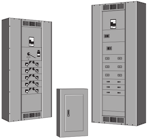
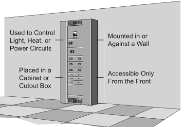
A panelboard is a type of enclosure for overcurrent protection devices and the busses and connections that provide power to these devices and their associated circuits. A panelboard is:
- Used to control light, heat, or power circuits
- Placed in a cabinet or cutout box
- Mounted in or against a wall
- Accessible only from the front
Panelboards are frequently divided into two categories:
- Lighting and appliance branch-circuit panelboards
- Power panelboards (also called distribution panelboards)
A lighting and appliance, branch-circuit panelboard had to have more than ten percent of its overcurrent protection devices (not including main devices) protecting lighting and appliance branch circuits. A lighting and appliance branch circuit is one with a connection to the panelboard neutral and an overcurrent protection device rated for 30 amps or less. For the purpose of this definition, each pole of a device is considered as one device. Additionally, a lighting and appliance panelboard was allowed a maximum of 42 overcurrent protection devices (poles) in any one cabinet or cutout box.
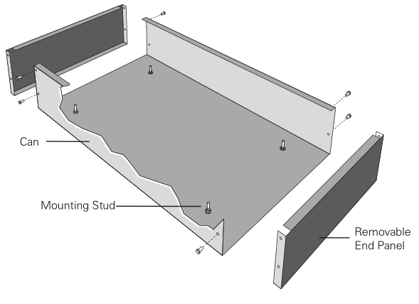
Panelboards are available in different sizes with variations in construction. The components that make up a panelboard, however, are similar. Panelboards contain a can, interior, circuit protection devices, label, and trim.
Can – The can is typically constructed of galvanized steel and houses the other components. The can is also referred to as a box or enclosure. It is designed to provide component and personnel protection
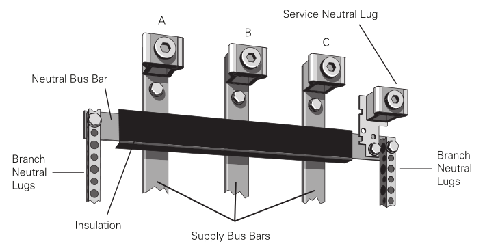
Interior – The interior consists of several components, including overcurrent protection devices, bus bars and insulated neutral bus bars.
Bus Bars – A bus bar is a conductor that serves as a common connection for two or more circuits. Standard bus bars on some panelboards are made of aluminum, but copper bus bars are available as an option.
High Leg – Some power supply systems use a transformer with a three-phase, four-wire (3Ø4W), delta-connected secondary with grounded, center-tap connection on one phase.
Split Neutral – Some panelboards feature a split neutral design which means that neutral connections are available on both sides of the panelboard. Split neutrals are connected by means of an insulated neutral bus bar.
Circuit Protection Devices – While it is common for load centers to have plug-in branch circuit breakers, circuit breakers used in panelboards for commercial and industrial applications typically bolt on to the bus bars.
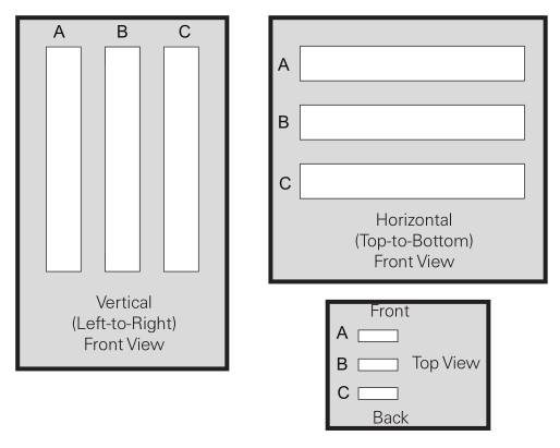
Circuit Identification – Specifications typically require panelboard circuit terminals to be labeled or for a wiring diagram to be provided. One approach for numbering terminals is to use odd numbers for poles on the panelboard’s right (your left as you face the panelboard) and even numbers on the panelboard’s left.
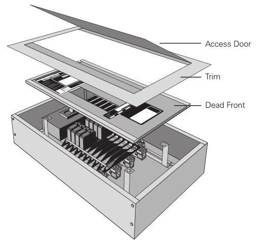
Dead Front and Trim – The dead front and trim are the front surfaces of the panelboard that cover the interior. The trim includes an access door. These components provide access to the overcurrent devices while sealing off the bus bars and internal wiring from contact.
Overcurrent Protection Devices
Because current flow in a conductor always generates heat, the greater the current flow, the hotter the conductor. Excess heat is damaging to electrical conductors. For that reason, conductors have a rated continuous current carrying capacity or ampacity. Current beyond the rated capability of a conductor is referred to as overcurrent. Overcurrent can result from a short circuit, an overload, or a ground fault.
Short Circuit – A short circuit occurs when two bare conductors touch causing the resistance between the conductors to drop significantly. This reduction in resistance causes an immediate and destructive increase in current. An overload is a typically a much lower current than a short circuit. An overload occurs when too many devices are connected to a circuit or when electrical equipment is made to work beyond its rated capabilities. Finally, a ground fault occurs when current takes an undesired path to ground. The level of ground fault current depends on the resistance of the path and the amount of voltage applied.
Overcurrent protection devices are used to protect conductors from excessive current flow. Some overcurrent protection devices only provide protection in the event of a short circuit, some provide both short circuit and overload protection, and some devices provide protection in the event of any of the three overcurrent types.
Circuit protection would be unnecessary if overcurrents could be eliminated. Unfortunately, overcurrents do occur and, when an overcurrent occurs, a protection device must automatically disconnect the electrical equipment from the voltage source. An overcurrent protection device must be also able to recognize the difference between a small overcurrent and a short circuit and
respond in the proper way. A small overcurrent is often allowed to continue for a short time, but, as the current magnitude increases, the protection device must respond faster. Short circuits must be interrupted immediately.
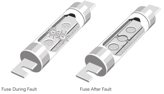
Fuse – A fuse is one type of overcurrent protection device. A fuse is a one-shot device. The heat produced by overcurrent causes the current carrying element to melt open, disconnecting the load from the source voltage.
- Non-time-delay Fuses – Non-time-delay fuses provide excellent short circuit protection. When an overcurrent occurs, heat builds up rapidly in the fuse. Non-time-delay fuses usually hold 500% of their rating for approximately one-fourth second, after which the current- carrying element melts. This means that these fuses cannot be used in motor circuits, which often have large in-rush currents when a motor starts.
- Time-delay Fuses – Time-delay fuses provide overload and short circuit protection. Time-delay fuses used in motor applications usually allow several times the rated current for a short time to allow motors to start without blowing the fuse.
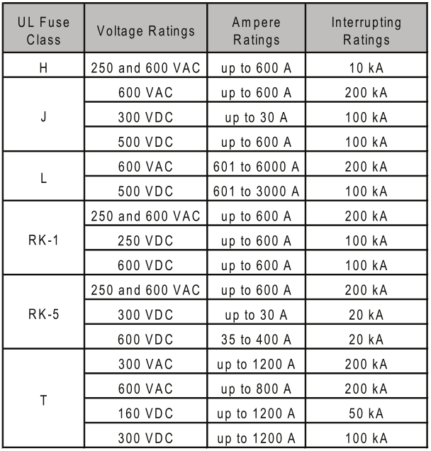
Fuse Classes – Underwriters Laboratories (UL) establishes and standardizes basic performance and physical specifications for products that undergo its safety test procedures. Among the standards developed by UL are standards for classes of low voltage fuses (fuses with voltage ratings of 600 volts or less).
Fuses are grouped into classes based on their operating and construction characteristics. Each class has an interrupting rating, which is the maximum current the fuse is capable of safely interrupting. Fuses also have maximum continuous current and maximum voltage ratings. The following table shows the fuse classes most commonly found in panelboards.
Fusible Disconnect Switch – A fusible disconnect switch is one type of device used on panelboards to provide overcurrent protection. Fuses located in the switch are selected to handle the specified levels of current and voltage and to provide the appropriate interrupting rating.
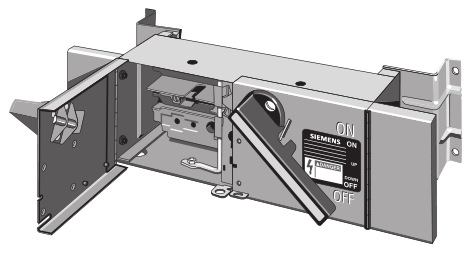
When the switch is moved to the OFF position, the movable contact snaps from between the jaws providing a quick, clean break. Twin arcs are produced which are smaller and extinguish quicker than a single arc produced by other designs.
The contacts are surrounded by an enclosed arc chamber which absorbs much of the heat from the arching. The enclosed chamber limits oxygen to more rapidly cool and extinguish arcs.
Circuit Breaker – Another device used for overcurrent protection is a circuit breaker. Although some circuit breakers do incorporate fuses, most do not, but, like a fusible switch, a circuit breaker provides overcurrent protection and a manual means of controlling power distribution.
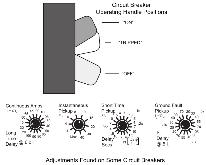
When an overcurrent occurs, the circuit breaker trips to remove power from the circuit. The greater the overcurrent, the more rapidly the circuit breaker trips. Once the overcurrent condition has been corrected, a simple flip of the breaker’s operating handle restores the circuit.
The ability to restore a circuit without replacing a fuse is one of the key advantages of a circuit breaker. However, circuit breakers have other advantages as well. For example, some circuit breakers have adjustments or a replaceable trip unit to allow the level of fault current required to trip the breaker to be set to match the application. Some circuit breakers also have communication capability to allow information to be sent to power monitoring equipment or display devices.
Circuit breakers are rated according to the maximum voltage they can handle. The voltage rating is a function of the circuit breaker’s ability to suppress the internal arc that occurs when the circuit breaker’s contacts open.
The voltage rating of the circuit breaker must be at least equal to the circuit voltage. The voltage rating of a circuit breaker can be higher than the circuit voltage, but never lower. For example, a 480 VAC circuit breaker could be used in a 240 VAC circuit, but a 240 VAC circuit breaker could not be used in a 480 VAC circuit.
Some circuit breakers have what is referred to as a “slash” voltage rating, such as 120/240 VAC or, as shown in the following graphic, 600/347 VAC for 2, 3, or 4-pole NEB breakers and 115/250 VDC for 2-pole NEB breakers. In such cases, the breaker may be applied in a circuit where the nominal voltage between any conductor and ground does not exceed the lower rating and the nominal voltage between conductors does not exceed the higher rating.
Every circuit breaker has a continuous current rating which is the maximum continuous current a circuit breaker is designed to carry without tripping. The current rating is sometimes referred to as the ampere rating because the unit of measure is amperes, or, more simply, amps.
Conductors are rated for how much current they can carry continuously. This is commonly referred to as the conductor’s ampacity. In general, the ampere rating of a circuit breaker and the ampacity of the associated conductors must be at least equal to the sum of any noncontinuous load current plus 125% of the continuous load current.
Circuit breakers are also rated according to the maximum level of current they can interrupt. This is the interrupting rating or ampere interrupting rating (AIR). Because UL and IEC testing specifications are different, separate UL and IEC interrupting ratings are usually provided.
When designing a power distribution system, a main circuit breaker must be selected that can interrupt the largest potential fault current that can occur in the selected application. The interrupting ratings for branch circuit breakers must also be taken into consideration, but these interrupting ratings will depend upon whether series ratings can be applied.
Backup Power
Facility managers have multiple tools at their disposal when looking for ways to improve the reliability of their electrical power system. For large facilities with critical operations, redundant electrical supplies offer one level of protection. Battery powered units with built-in inverters can offer short-term protection for smaller loads. But for most applications, the most commonly applied means of improving the reliability of a facility’s electrical supply is the backup generator. And for those facilities with loads that cannot tolerate even a momentary loss of power, or that require a clean, stable source of power, there is the UPS system.
Backup Generator – The natural gas, propane, or diesel generator is the most widely used alternative source of power in facilities today. Its ability to provide continuous power as long as it has a supply of fuel makes it well-suited for providing both long- and short-term backup power.
Most generator-based systems are designed to automatically provide power to designated loads in the event of an interruption in service. When power is lost, the generator automatically starts. Once the generator comes up to speed, a switch automatically transfers the load from utility power to the output of the generator. Depending on the size of the generator, this transfer typically takes place in 30 seconds or less. Once utility company power is restored, the load is transferred back and the generator shuts down.
While generator systems are very reliable, they are not maintenance-free. If the systems are to perform as needed, when needed, they must have regularly scheduled maintenance.
One of the most important maintenance tasks that can be performed with generator-based systems is the regular exercising of the entire system. Once each week or two, depending on the size of the generator and the nature of the loads it must supply, generators should be started and run for at least 30 minutes. To fully test the entire system, the generators should be run under load — ideally the load that it would normally power. By operating the system under load for 30 minutes, the generator is tested along with its starting system, cooling system, and all switchgear required to supply power to the loads.
In addition to the program of regular exercising, there are a number of other routine maintenance tasks that must be performed. The batteries used to start the generator should be checked monthly. Each time the generator is run or exercised, the fuel supply should be inspected to determine how much is present and to ensure that it is free of contamination. Additionally, the generator’s cooling and exhaust systems should be inspected once each month.
The UPS System – While generators offer long-term protection in the event of an interruption of service, they cannot offer protection against many of the common faults in power systems. That level of protection can be achieved only with an uninterruptible power supply (UPS). While there are several different configurations for UPS systems, the most commonly used is the online system.
The online UPS has three major components: a charger/rectifier, storage batteries and a power inverter. Incoming alternating current from the utility company enters the charger/rectifier where it is converted to direct current. This direct current charges the batteries and supplies power to the inverter which converts the direct current back to alternating current. In systems designed to power loads during extended outages, a generator is typically connected to the batteries.
The UPS system offers the advantage of supplying power to the loads continuously, no matter what happens to the utility power. But the benefits of the UPS go beyond its ability to continuously supply power. The process of taking alternating current from the utility and converting it to direct current, then back to alternating current, eliminates practically all power disturbances, including transients, noise, and voltage fluctuations.
UPS systems, like generators, are only as reliable as the maintenance that is performed on them. For example, most systems use lead acid batteries to supply power during service interruptions and while the generator is getting up to speed. These batteries require regular inspections to ensure that all cable connections are free of corrosion and are properly torqued. Electrolyte level within the batteries must be kept at the proper height to prevent damage to the batteries. Batteries must also be tested every six months to check for capacity loss.
Other components in the UPS system require less maintenance, but still should be inspected on a regular basis to ensure that they are free of dust that might result in overheating and that all connections are properly torqued.
The electrical switchgear that connects the backup generator or the UPS system to the facility’s loads forms the backbone of the power system. With the UPS system, the loads are connected to distribution panels that are wired to the output of the system. Loads in generator-based systems are connected to distribution panels that are wired to an automatic transfer switch. Utility power is normally connected to the loads through the transfer switch. When utility power is interrupted and the generator is producing power, the switch automatically transfers the load to the output of the generator. When utility power is restored, the switch automatically transfers the load back to the utility.
Electrical switchgear typically is a long-life, low-maintenance item. Because it is reliable and does not require much maintenance, it is the most overlooked component in the system. A malfunction in the switchgear, however, can prevent an otherwise perfectly operating system from coming online. Additionally, malfunctions within the switchgear can result in damage to the switchgear itself.
Most damage to electrical switchgear is caused by a combination of water, dust, high humidity levels and vibration. Moisture and dust combine to form an insulating layer on surfaces, reducing heat transfer from the components and increasing component operating temperatures. Similarly, moisture and dust coat components, restricting their movement and causing excessive wear. Vibrations can cause terminations to come loose.
At least once each year, all switches, disconnects, and circuit breakers should be exercised to verify that they are not binding. At the same time, all contacts and connections within the system should be inspected for pitting, discoloration and tightness.
Avoiding Common Pitfalls – Backup power systems are very reliable, and good maintenance practices can keep them that way for a long time. And while the systems may be fully automatic, they do require some careful planning during installation and once the systems become operational.
For example, during a prolonged power outage, it will be necessary to arrange for fuel deliveries for propane gas and diesel generators. Contracts with suppliers should be set up ahead of time with guaranteed delivery schedules. If a facility manager waits until the generator is already running to figure out how fuel is going to be supplied to the unit, maintenance personnel may be forced to shuttle fuel in five gallon cans, a practice that is unsafe and unreliable.
Care must be taken when planning the location of a backup power system. Generators are noisy units that create vibrations and give off exhaust fumes. Units must be located in such a way that they do not interfere with operations, yet are fairly close to the facility’s power distribution panels so that they can be tied in relatively easily.
UPS systems also must be carefully sited. These systems and their batteries generate large quantities of heat under normal operation. Without adequate ventilation, a buildup of heat will shorten the lives of the batteries and other components. Good ventilation is also required to prevent a buildup of hydrogen gas, which is a normal byproduct of the battery charging process.
In addition, it’s important to make certain that all required loads are properly connected to the system. Over time, power requirements within the facility change. New loads are added while old ones are removed or relocated. At least once each year, the facility should be reviewed for backup power requirements. Failing to do so may result in a perfectly operating backup power system that is not connected to the required loads.
Power outages can occur at any time. As a result, personnel who are most familiar with how to operate and monitor the backup power system may not be on-site at the time of the outage. Therefore it is essential to have well written procedures detailing what should be done in the event of an outage. These procedures must cover everything from what to do if the system does not start to how to monitor the health of the system while it is operating.
Maintenance
The failure rate of electrical equipment is three times higher for components that are not part of a scheduled preventive maintenance program as compared with those that are. We discuss, maintenance for electrical devices involved in electricity distribution.
Switchgear – Ensure that all enclosure panels, doors, and structures are well- maintained in accordance with the manufacturer’s specifications. During de-energized maintenance, enclosures are to be vacuum cleaned of all loose dirt and debris — use of compressed air is not recommended since this may cause foreign particles to become embedded in the insulation or damage insulators.
Any buildup of dirt or other contaminates that will not come off with vacuuming should be cleaned with lint free rags using cleaning solvents recommended by the manufacturer. All vents and fan grills are to be cleaned of all dust and/or dirt accumulations. Ensure that ventilation openings are not obstructed. Where seals and/or gaskets are installed, these should be examined and repaired or replaced as necessary. All doors and access panels should be properly secured during operation. Where heater elements are installed, these should be cleaned, examined for damage and/or deterioration, and tested. Repair or replace heater elements as necessary.
Electrical equipment rooms or vaults should be examined for evidence of water seepage. The tops of electrical equipment enclosures should be examined for evidence of water since this is a common entryway that often goes undetected until a failure occurs. The source of the water should be immediately identified and corrective measures taken to permanently correct the condition.
Inspect insulators and conductor supports for signs of cracking, broken pieces, and other physical damage or deterioration. Clean all loose dirt with lint free rags. For contaminates that will not remove easily, solvents approved by the manufacturer may be used. Examine for evidence of moisture that may lead to tracking or flashover while in operation. Examine surrounding areas for signs of tracking, arcing, or overheating. Repair or replace damaged insulators and supports as necessary.
Examine all bolts and connecting devices for signs of deterioration, corrosion, or overheating. Ensure that bolts and connecting devices are tight, according to manufacturer’s specifications. Be careful not to over-torque bolts and connecting devices since insulators are easy to damage and difficult to replace.
Examine insulation for signs of deterioration, cracking, flaking, or overheating. Examine all connections for signs of overheating, cracked or broken connectors, and signs of tracking or arcing. Ensure that conductors are clean and dry. Examine and clean all connections, and torque to manufacturer’s recommendations.
Air Circuit Breakers – Remove and clean inter-phase barriers. Clean all insulating materials with vacuum and/or clean lint free rags. If it is necessary to use cleaning solvents, use only solvents recommended by the manufacturer. Inspect for signs of corona, tracking, arcing, or thermal or physical damage. Ensure that insulation is left clean and dry.
Ensure that all contacts are clean, smooth, and in proper alignment. Ensure that spring pressures are maintained according to manufacturer’s specifications. On silver contacts, discoloration is not usually harmful unless caused by insulating deposits. Clean silver contacts with alcohol or silver cleaner using non-abrasive cloths.
Manually close breaker to check for proper wipe, contact pressure, contact alignment, and to ensure that all contacts make at approximately the same time. If possible, a contact resistance test should be performed to determine the quality of the contacts. Ensure any lubrication is done according to the manufacturer’s specifications.
Oil Circuit Breakers – Inspect the enclosure for signs of oil leakage. Clean external bushings assemblies and examine for signs of deterioration, tracking, and loose or broken parts. Observe oil gauge to ensure device is operating properly and measuring the oil level accurately.
Conduct a dielectric screen test of the insulating fluid. Based on the results of this test, filter or replace oil as required. Heavy carbon content can indicate potential contact wear and should be investigated further.
Follow manufacturer’s recommended schedule for examination of internal components such as contact inspections. Open breaker and examine contacts for wear and/or excessive deterioration. Examine linkages for loose, broken, or missing parts; repair or replace as necessary.
Batteries – Thoroughly clean all battery surfaces of dust and/or dirt accumulations. Clean and tighten all terminal connections. Remove any corrosion on battery terminals with bicarbonate of soda. Clean battery studs and cable ends. On stranded cable, if ends are corroded, cut off ends or separate strands and clean internally. Check electrolyte levels and specific gravity. Variations of more than fifty points between cells may indicate a bad cell.
While charging, batteries emit explosive gases. Allow no open flames or sparks permitted near charging batteries. Battery rooms should be well ventilated and smoking should not be permitted.
Cables and Bus – De-energize cables if they are to be touched or moved during maintenance. All loose or dirty connections should be cleaned and properly torqued — be careful not to overtorque the bolts. Inspect for sharp bends, physical damage, excessive tension, oil leaks, pits, cable movement, soft spots, cracked jackets, damaged fireproofing, poor ground connections, deteriorated and corroded or weakened cable supports. Inspect for wear at entrance point and at supports. Inspect manhole for spalled concrete, proper ventilation and excessive moisture.
Transformers – Transformer data (such as, voltage, current, and temperature readings) should be recorded on a regular basis in order to determine operating conditions of the transformer. Peak,
or redline, indicators should be recorded and reset. Readings taken on a weekly basis can provide
important information about the loading of the transformer that is needed before additional loads can be added to the transformer.
After de-energizing and grounding the transformer, clean all coils, connections, and insulators of loose dust or dirt deposits with a vacuum cleaner. Examine the transformer for signs of overheating, deterioration, arcing, loose or broken parts, or other abnormal conditions.
UPS Systems – Clean interior and exterior of cabinets and enclosures, ensuring that any areas of corrosion and/or deterioration are repaired as necessary. Clean all vent and air circulation openings and ensure freedom from obstructions. If installed, clean cooling fan blades and motor housings. Ensure that motor bearings are properly lubricated and that fan blades are properly secured to drive shafts. Examine for signs of moisture contamination and correct if necessary.
Clean and examine all electrical connections for signs of corrosion or deterioration, repair or replace as necessary. Ensure all connections are tightened according to manufacturer’s specifications. As applicable, clean and test all breakers, disconnects, and relays as prescribed elsewhere in these standards and as specified by the manufacturer. Check all system alarms and indicating lights for proper operation. Check inverters for fluid leaks from wave-forming capacitors. Check capacitors for signs of bulging or discoloration. Examine transformers and heat sinks for signs of overheating.
