A network is a collection of computers and other hardware components interconnected by communication channels that allow sharing of resources and information. Networking is the practice of linking two or more computing devices together for the purpose of sharing data. Networks are built with a mix of computer hardware and computer software. A host device on a network can be computers, servers, laptops, Personal Digital Assistants (PDAs), or anything a person uses to access the network. Network devices are hubs, repeaters, bridges, switches, router and firewall.
Network Models (Peer-to-Peer and Client-and-Server)
The term computer network model defines the category in which a computer network can be grouped into. Networks are divided into peer to peer and client-server.
Peer To Peer Networks
When nodes or workstations perform the same communication functions, they are referred to as peers, in this network model, both server and client operations are performed by the same computer. Each user administers his/her workstation and the resources in it. There are no dedicated servers and no hierarchy among the computers. All the computers are equal and therefore are known as peers. Each computer functions as both a client and a server, and there is no administrator responsible for the entire network. The user on each computer determines which data on that computer is shared on the network.
Security is also managed by the user of the devices. This model is not quite secure and is suited for a small computer networks (with 10 computers or less) where users do not want to share files. User’s files are decentralized – they are not stored in a single location.
Client Server Networks
This network model offers centralized access to services and devices. One computer plays the role of a server. It is the most common type of network architecture today that provides centralized data storage, security, manning of applications and network administration. Most servers have operating system like Windows NT/2003 or later, Linux, Novel Netware etc.
Network Types (LAN,WAN,MAN,PAN)
Different types of networks are distinguished based on their size (the number of nodes), their data transfer speed, and their reach. Private networks are networks that belong to a single organization. There are usually of three categories
- LAN (local area network)
- MAN (metropolitan area network)
- WAN (wide area network)
There are two other types of networks as PANs (Personal Area Network), which are limited few feets, and CANs (Campus Area Networks), which are the same as MANs (with bandwidth limited between each of the network’s LANs).
LAN
It’s a group of computers which all belong to the same organization, and which are linked within a small geographic area using a network, and often the same technology (usually Ethernet). Data transfer speeds over a local area network can be up to 10 Mbps, 1 Gbps and 10 Gbps. LAN can reach to 100 or even 1000 users. LAN can be sub-divided as per the services that it provides and operating modes into, a “peer-to-peer” network (having no central computer and each computer has the same role) and a “client/server” network (with a central computer for services to users).
MAN
MANs (Metropolitan Area Networks) connect multiple geographically nearby LANs to one another (over an area of few kilometres) at high speeds. Thus, a MAN lets two remote nodes communicate as if they were part of the same local area network. A MAN is made from switches or routers connected to one another with high-speed links (usually fiber optic cables or microwave).
WAN
A WAN (Wide Area Network or extended network) connects multiple LANs to one another over vast geographic distances. The speed available on a WAN varies depending on the cost of the connections (which increases with distance) and may be low. WANs operate using routers, which can “choose” the most appropriate path for data to take to reach a network node. The most well-known WAN is the Internet.
Internet connection (DSL, Cable, Serial Link)
The need for speed has changed the options available to consumers and businesses. The connection speeds will change over time and also between Internet Service Providers (ISP). Various internet connection technologies have different characteristics and are discussed.
Dial-up Internet Access
It is called as dial-up access and is economical but slow. Users connect by a modem linked to PC by dialing a phone number (from ISP) but tying up phone line. It is an analog connection as data is sent over an analog, public-switched telephone network. The modem converts received analog data to digital and vice versa. Due to telephone lines usage, the quality of the connection is not always good and data rates are limited. The connection speeds range from 2400 bps to 56 Kbps.
ISDN – Integrated Services Digital Network
It is an international communications standard for sending voice, video, and data over digital telephone lines or normal telephone wires and speeds are from 64 Kbps to 128 Kbps.
B-ISDN – Broadband ISDN – Broadband ISDN is similar in function to ISDN but it transfers data over fiber optic telephone lines, not normal telephone wires. SONET is the physical transport backbone of B-ISDN. Broadband ISDN has not been widely implemented.
DSL – Digital Subscriber Line
DSL uses existing telephone line and gives internet simultaneously with telephone service without tying up phone line. Two main categories of DSL for home are called ADSL and SDSL. All types of DSL technologies are collectively called xDSL with speeds from 128 Kbps to 9 Mbps.
ADSL – Asymmetric Digital Subscriber Line – ADSL is the most commonly deployed types of DSL in North America. It supports data rates of from 1.5 to 9 Mbps when receiving data or downstream rate and from 16 to 640 Kbps when sending data or the upstream rate.
ADSL+2 – ADSL Extension – An extension to ADSL broadband technology with faster download speeds though similar as ADSL. Both use a special filter on a telephone line to split existing telephone lines (POTS) between regular telephone (voice) and ADSL+2.
Cable – Broadband Internet Connection
It uses a cable modem for Internet connection over cable TV lines. It works by using TV channel space for data transmission, with certain channels used for downstream transmission, and other channels for upstream transmission. As, the coaxial cable is used so, greater bandwidth is present. Cable speeds range from 512 Kbps to 20 Mbps.
Wireless Internet Connections
Wireless Internet, or wireless broadband is the newest Internet connection types. It uses radio frequency bands for transmission. It provides an always-on connection which can be accessed from anywhere but within a network coverage area hence, it is not present in some areas. It is usually more expensive and mainly available in metropolitan areas by cellular operators using 2Gor 3G.
T-1 Lines – Leased Line
T-1 lines are a leased line option connecting to the Internet backbone with a dedicated phone connection supporting data rates of 1.544Mbps. A T-1 line consists of 24 individual channels, each supporting 64Kbits per second and can be configured to carry voice or data traffic. One or some of individual channels can be taken, and called as fractional T-1access.
T-3 Lines – Dedicated Leased Line – T-3 lines are similar to T-1 with data rates of about 43 to 45 Mbps. It consists of 672 individual channels, each of which supports 64 Kbps.
Network Media
Network media is the actual path over which data travels as it moves from one component to another. The network transmission medium carry signals between computers. There is a variety of media that meet the varying needs and sizes of networks and the common types are coaxial, twisted-pair, unshielded twisted-pair, shielded twisted-pair, fiber-optic and wireless
Coaxial Cable
It has a hollow outer cylindrical conductor that surrounds a single inner wire made of two conducting elements usually copper and surrounding it, is a layer of flexible insulation. Over this insulating material is a woven copper braid or metallic foil that acts both as the second wire in the circuit and as a shield for the inner conductor. This second layer, or shield, can help reduce the amount of outside interference. Covering this shield is the cable jacket.
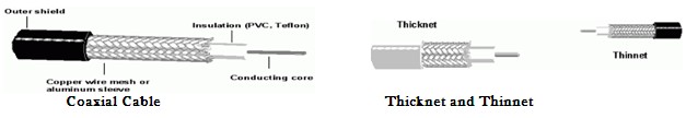
It supports 10 to 100 Mbps and is more costly than UTP but, can be cheaper for a physical bus topology as less cable will be needed. Coaxial cable can be cabled over longer distances than twisted-pair cable usually 500m compared to 100m for UTP. The largest diameter (1 cm) coaxial cable is referred as Thicknet but, it is too rigid to install easily due to its thickness. A connection device called vampire tap connect network devices to Thicknet by attachment unit interface (AUI). Similarly, coaxial cable with an outside diameter of only 0.35 cm is referred as Thinnet and used with networks with many twists and turns. Thinnet uses BNC (British Naval Connector or Bayonet Neill Concelman) connectors which are a male type mounted at each end of a cable.
Twisted-Pair Cable
Twisted-pair cable is a type of cabling that is used for telephone communications and Ethernet networks. A pair of wires forms a circuit that can transmit data. The pairs are twisted to provide protection against crosstalk, the noise generated by adjacent pairs. Using cancellation with twisting the wires, self-shielding for wire pairs within the network media is provided. Two basic types of twisted-pair cable exist of unshielded twisted pair (UTP) and shielded twisted pair (STP).
Unshielded Twisted-Pair (UTP) Cable
It relies on cancellation effect by the twisted wire pairs to limit signal degradation due to electromagnetic interference (EMI) and radio frequency interference (RFI). The number of twists in the wire pairs varies to reduce crosstalk between the pairs. UTP cable has four pairs of either 22- or 24-gauge copper wire. UTP external diameter is 0.43 cm and is easy to install and less expensive than other types of media. It is installed by a Registered Jack 45 (RJ-45) connector. UTP cable is more prone to electrical noise and interference also, the distance between signal boosts is shorter for UTP than others. Commonly used types of UTP cabling are as follows:
- Category 1—Used for telephone communications. Not suitable for transmitting data.
- Category 2—Capable of transmitting data at speeds up to 4 megabits per second (Mbps).
- Category 3—Used in 10BASE-T networks. Can transmit data at speeds up to 10 Mbps.
- Category 4—Used in Token Ring networks. Can transmit data at speeds up to 16 Mbps.
- Category 5—Can transmit data at speeds up to 100 Mbps.
- Category 5e —Used in networks running at speeds up to 1000 Mbps.
- Category 6—It has four pairs of copper wires and is the fastest standard for UTP.
Shielded Twisted-Pair (STP) Cable
Each of four pair of STP wires is wrapped in a metallic foil and then are wrapped in an overall metallic foil thus, reducing electrical noise within the cable (pair-to-pair coupling, or crosstalk) and from outside the cable (EMI and RFI). It is installed with STP data connector but, is more expensive and difficult to install. It’s speed and throughput are from 10 to 100 Mbps with maximum cable length to 100 m.
Fiber Optic Cable
It is a flexible, transparent fiber made of glass (silica) or plastic, thicker than a human hair. It functions as a waveguide to transmit light between the two ends of the fiber. It enables transmission over longer distances and at higher data rates. Optical fibers have a transparent core surrounded by a transparent cladding material with a lower index of refraction. Light is kept in the core by total internal reflection. This causes the fiber to act as a waveguide. Fibers supporting many propagation paths are multi-mode fibers (MMF) and a single mode are called single-mode fibers (SMF). MMF has a wider core diameter, and is used for short-distance but SMF are used for links longer than 1 km. Each fiber can carry many independent channels, each using a different wavelength of light. Speed varies from 5Mbps to 50Gbps and newer are in Tbs.
Wireless
It avoids using cables by using radio communication. It is used by two-way radios, GPS units, cellular telephones, personal digital assistants (PDAs), wireless networking, wireless computer mice or keyboards or headsets, satellite television and cordless telephones. IEEE 802.x (Wi-fi) standards are used for wireless computer network and are of different speeds and coverage area as 802.11 a/b/g/n.
Layered Network Model
The layered network model defines a networking framework for implementing protocols in different layers. Control is passed from one layer to the next, starting at the top most layer in one station, proceeding to the bottom layer, over the channel to the next station and back up the hierarchy.
The International Standards Organization (ISO) defined a seven-layer model to standardize networking processes. The benefits to layering networking protocol specifications are many including
- Interoperability – Greater interoperability between devices from different manufacturers and between different generations of same type of device from the same manufacturer.
- Compatibility – Compatibility between devices, systems and networks that this delivers.
- Better Flexibility – Improved flexibility in options and choices for configuration and installation.
- Increased Life Expectancy – Devices from different technology generations can co-exist thus the older units do not get discarded immediately newer technologies are adopted.
- Scalability – Experience shows that a layered design scales better than the horizontal approach.
- Value Added Features – It is easier to add and implement value added features into products or services when the entire system has been built on the use of a layered philosophy.
- Modularity Plug-ins and add-ons are easily added from use of a layered approach.
- Standardization and Certification –The layered design specifications facilitate streamlined and simple standardization and certification process due to the clearer and more distinct definition.
- Portability – Layered networking protocols are much easier to port from one system to another.
- Compartmentalization of Functionality – It gives freedom to concentrate on a specific layer or specific functions without the need for concern or modification of any other layer.
TCP/IP Protocol Architecture
TCP/IP provides end-to-end connectivity specifying how data should be formatted, addressed, transmitted, routed and received at the destination. The TCP/IP model and related protocols are maintained by the (IETF) or Internet Engineering Task Force. The Internet protocol suite and the layered protocol stack design were in use before the OSI model was established. It has four abstraction layers, each with its own protocols. It has four abstraction layers, each with its own protocols. From highest to lowest, the layers are
- Application layer (process-to-process)– It contains all protocols (like HTTP) for specific data communications services on a process-to-process level (for example how a web browser communicates with a web server). This is the scope within which applications create user data and communicate this data to other processes or applications on another or the same host. The communications partners are often called peers. This is where the “higher level” protocols such as SMTP, FTP, SSH, HTTP, etc. operate.
- Transport layer (host-to-host)- It handles host-to-host communication. The transport layer constitutes the networking regime between two network hosts, either on the local network or on remote networks separated by routers. The transport layer provides a uniform networking interface that hides the actual topology (layout) of the underlying network connections. This is where flow-control, error-correction, and connection protocols exist, such as TCP. This layer deals with opening and maintaining connections between Internet hosts.
- Internet layer (internetworking)- It connects local networks, thus establishing internetworking. The internet layer has the task of exchanging datagrams across network boundaries. It is therefore also referred to as the layer that establishes internetworking, indeed, it defines and establishes the Internet. This layer defines the addressing and routing structures used for the TCP/IP protocol suite. The primary protocol in this scope is the Internet Protocol, which defines IP addresses. Its function in routing is to transport datagrams to the next IP router that has the connectivity to a network closer to the final data destination.
- Link layer- The link layer (commonly Ethernet) contains communication technologies for a local network. This layer defines the networking methods within the scope of the local network link on which hosts communicate without intervening routers. This layer describes the protocols used to describe the local network topology and the interfaces needed to affect transmission of Internet layer datagrams to next-neighbor hosts.
Application Layer
It contains all protocols and methods of process-to-process communications across an Internet Protocol (IP) network. Its methods use the underlying transport layer protocols to establish host-to-host connections. Both TCP/IP and the OSI model specify a group of protocols and methods identified by the name application layer. The following protocols are described in the application layer of the Internet protocol suite.
- Remote login – Telnet
- File transfer – FTP, TFTP
- Electronic mail – SMTP,IMAP, POP
- Support services – DNS, RARP, BOOTP, SNMP
Transport Layer
The transport layer or layer 4 provides end-to-end communication services for applications by providing services like connection-oriented data stream support, reliability, flow control, and multiplexing. It is contained in the TCP/IP as TCP and in the OSI model as transport layer.
The Transmission Control Protocol (TCP) is used for connection-oriented transmissions, whereas the connectionless User Datagram Protocol (UDP) is used for simpler messaging transmissions. TCP has stateful design for reliable transmission and data stream services. Various services provided by a transport-layer protocol include
- Connection-oriented communication- Interpreting the connection as a data stream provides benefits to applications.
- Byte orientation- It is easier to process data stream as a sequence of bytes helping various underlying message formats.
- Same order delivery- The network layer doesn’t guarantee data packet arrival in the same order that they were sent, hence segment numbering is used, with the receiver passing them to the application in order.
- Reliability- Packets may be lost due to network congestion hence, an error detection code like checksum checks data corruption, and verify correct receipt by sending an ACK or NACK message to sender. Automatic repeat request retransmits lost or corrupted data.
- Flow control- The rate of data transmission between two nodes is managed to prevent a fast sender for more data. It also improves efficiency by reducing buffer under run.
- Congestion avoidance- It controls traffic entry into a network by avoiding oversubscription of link capabilities of intermediate nodes and networks by reducing rate of sending packets.
- Multiplexing- Ports provide multiple endpoints on a single PC like the name on a postal address is a multiplexing, and differs between different recipients at same location. Computer applications each listen for information on their own ports, which enables the use of more than one network service at the same time.
Internet Layer or IP Layer
It is a group of internetworking methods, protocols, and specifications used to transport datagrams (packets) from the originating host across network, to destination host specified by a network address (IP address). It facilitates internetworking or connecting multiple networks by gateways.
Internet-layer protocols use IP-based packets and have three functions, for outgoing packets, select the next-hop host (gateway) and transmit the packet to this host by passing it to the appropriate link layer implementation; for incoming packets, capture packets and pass the packet payload up to the appropriate transport-layer protocol, if appropriate. In addition it provides error detection and diagnostic capability. The Version 4 of the IP (IPv4), IP is capable of automatic fragmentation or de-fragmentation of packets, based on the maximum transmission unit (MTU) of link elements.
It is not responsible for reliable transmission and offers “best effort” delivery hence, no proper arrival making network resilient and assigning reliability provision to higher level protocols. In IPv4 (not IPv6), a checksum is used to protect the header of each datagram.
Network Access Layer
It is the lowest layer which provides the means for the system to deliver data to the other devices on a directly attached network. It defines how to use the network to transmit data and thus, must know the details of the underlying network to correctly format the data being transmitted to comply with the network constraints. The TCP/IP Network Access Layer has the functions of all three lower layers of OSI (Network, Data Link, and Physical).
Functions performed at this level include encapsulation of IP datagrams into the frames transmitted by the network, and mapping of IP addresses to the physical addresses used by the network. One of TCP/IP’s strengths is its universal addressing scheme. The IP address must be converted into an address appropriate for physical network over which the datagram is transmitted.
Devices at different layers
Devices at different layers of TCP/P network model are
- Layer 1- It is the physical layer. Media converters operate at Layer 1 to convert electrical signals and physical media without doing anything to data coming through the link. Media converters have two ports—one in, one out— to convert the incoming electrical signal from one cable type and then transmit it over another type.
- Layer 2- It is the data-link layer. Switch and media converter operate at Layer 2 to sort packets using physical network addresses or MAC addresses. All network hardware is permanently assigned this number during its manufacture. Both switches and media converters can be Layer 2 devices. A switch has more ports than a media converter. Devices are fast, but aren’t smart as they don’t look at data packets closely.
- Layer 3- It is the Network Layer and layer 3 switches use network or IP addresses to identify locations on the network. Layer 3 switches are smarter due to routing functions to find the best way to send a packet to its destination.
- Network Router – A router routes data packets between two networks by reading the destination information in each packet so, for an immediate network it has access to, it will strip the outer packet, readdress the packet to the proper Ethernet address, and transmit it but, for another network destination it is sent to another router, re-package outer packet to receive by next router and send it to next router.
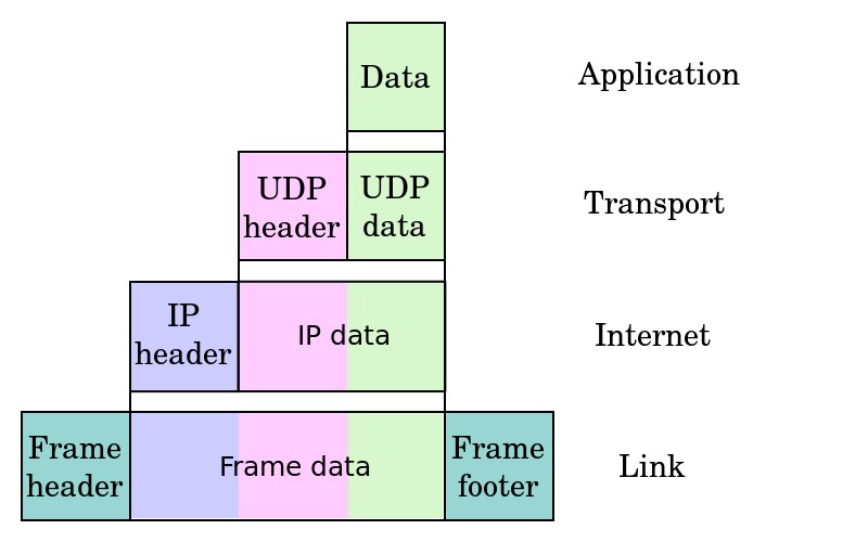
Data Encapsulation
It is a method for communication protocols to logically separate functions in the network and abstracts it from their underlying structures by inclusion or information hiding within higher level objects. Link encapsulation by the physical layer allows local area networking by higher layers and IP provides global addressing of individual computers; UDP adds application or process selection, i.e., the port specifies the service such as a Web or TFTP server.
The more abstract layer is called the upper layer protocol while the more specific layer is called the lower layer protocol. Encapsulation is a characteristic feature of most networking models, including the OSI Model and TCP/IP suite of protocols. An image of encapsulation of application data descending through the layers.
Internet Protocol
The OSI physical layer and data link layer do not define how to deliver data between devices interconnected with multiple devices. The OSI network layer provides the end-to-end delivery of data between endpoints with any type of physical network in between. The network layer specifies data routing. IP is the primary protocol in the Internet Layer of the Internet Protocol Suite and has the task of delivering datagrams from the source host to the destination host solely based on the addresses. For this purpose, IP defines datagram structures that encapsulate the data to be delivered. It also defines addressing methods that are used to label the datagram source and destination. OSI network layer has following functions which include
- Logical addressing – Sending the data packet from one network to another network requires logical addressing. It helps to distinguish source and destination systems. Network layer adds header to data coming from upper layers and include logical address of sender and receiver. Every host in the network must have a unique address that determines where it is. This address is normally assigned from a hierarchical system.
- Routing – As networks are divided into subnetworks and connect to other networks for wide-area communications, networks use gateways or routers to route packets to their final destination. It is also called as the process of forwarding packets (Layer 3 PDUs)
- Routing protocol – A protocol used by routers to learn dynamically about addresses in a network, for decision making during routing or forwarding process.
IP Routing
Data packet is routed from source to destination by passing through one or more routers and networks. The IP Routing protocols enable routers to build up a forwarding table to relate an final destination address with next hop addresses. Various protocols used in routing are BGP (Border Gateway Protocol), IS-IS (Intermediate System – Intermediate System), OSPF (Open Shortest Path First) and RIP (Routing Information Protocol).
IP routing is done on a hop-by-hop basis. IP does not know the complete route to any destination (except directly connected). IP routing provides the IP address of the next-hop router to which the data is sent and the next-hop router is assumed to be closer to destination. IP routing performs the following actions
- Search the routing table for an entry that matches the complete destination IP address (matching network ID and host ID). If found, send the packet to the indicated next-hop router or to the directly connected interface.
- Search the routing table for an entry that matches just the destination network ID. If found, send the packet to the indicated next-hop router or to the directly connected interface. All the hosts on the destination network can be handled with this single routing table entry.
- Search the routing table for an entry labeled “default.” If found, send the packet to the indicated next-hop router.
If none of the steps works, the datagram is undeliverable. If the undeliverable datagram was generated on this host, a “host unreachable” or “network unreachable” error is normally returned to the application that generated the datagram. Each entry in routing table has
- Specification of which network interface the datagram should be passed to for transmission.
- Destination IP address. It is either a host address or network address, as specified by the flag field. A host address with a nonzero host ID identifies one particular host, while a network address has a host ID of 0 and identifies all the hosts on that network.
- IP address of a next-hop router or directly connected network. The next-hop router is not the final destination, but it forwards data to the final destination.
- One flag specifies whether the destination IP address is the address of a network or the address of a host. Another flag says whether the next-hop router field is really a next-hop router or a directly connected interface.
IP routing protocols load routing tables with valid, loop-free routes and involves functions as
- Placing the best route, if more than one route to a subnet is available.
- Removing invalid routes from the routing table.
- Dynamically learn and load routing table for a route to all subnets in the
- Replace lost routes, quickly with best available route, also called convergence time.
- Preventing routing loops.
Every routing protocols publicizes it’s routes as
- Add a route for each subnet directly connected to it.
- Update neighbor router about all directly connected and learned routes.
- Add new routes from neighbors
IP Addressing
An IP address is a 32 bit binary number, looks like the following
00000100 10000000 00000011 00000001
It is divided into four 8-bit chunks, called octet, and represented into decimal number for humans to understand like 4.128.3.1 An IP address consists of two parts
- The leftmost bits specify the network address component, called network ID.
- The rightmost bits specify the host address components, called host ID.
Hosts on a network can communicate with devices in the same network by MAC address but for different networks, a router to move data is needed. Each LAN has a unique network ID and all hosts on that network have same network ID but different host ID. A network ID enables a router to put a packet onto the correct network segment. To decide which network is correct, the router looks up a routing table, which is a table contains entries for network addresses (network ID + all host bits set to 0). Each network interface uses a unique IP address.
IP addresses are broken into classes to accommodate different sizes of networks as
- Class A (1-126)- It supports extremely large networks and uses only first octet for the network address and rest three octets for host addresses. The first bit of a Class A address is always 0 but, the lowest number represented is 00000000 (decimal 0), and highest number is 01111111 (decimal 127) both are reserved and cannot be used as a network address. Any address start with 127 is reserved for loopback.
- Class B (128-191)- It supports middle-sized and large-sized networks with first two octets for network address and rest two octets for host addresses. The first two bits of a Class B address is binary number 10; thus, the lowest number represented is 10000000 (decimal 128) and highest number is 1011111 (decimal 191).
- Class C (192-223)- It supports small-sized networks with first three octets for network address and remaining one octet for host addresses. The first three bits of a Class C address is binary number 110 thus, lowest number represented is 11000000 (decimal 192), and the highest number is 11011111 (decimal 223).
- Class D- 224-239 is reserved for multicasting, for a single station to simultaneously transmit a datagrams to multiple recipients. It’s first four bits is binary number 1110.
- Class E- 240-255 is experimental addresses, reserved by the IETF for its research.
The block at the beginning and end of each class is called network address and broadcast address, respectively. These two special IP addresses are reserved and detailed as
- Network address- It has all host bits set to 0 to identify the network itself and cannot be assigned like 46.0.0.0 is the network address of the network containing the host 46.4.64.21.
- Broadcast address- It has all host bits set to 1 and used to send data to all the devices on a network like 46.255.255.255 is the broadcast address of network with host 46.4.64.21. Routers will forward broadcast packets on all interfaces but usually routers disable broadcast-forwarding.
The list of the Class A, B, C, D, E IP address is summarized as
| Class | Leading bits | Start | End | Network Bits | Host Bits |
| A | 0.0.0.0 | 127.255.255.255 | 8 | 24 | |
| B | 10 | 128.0.0.0 | 191.255.255.255 | 16 | 16 |
| C | 110 | 192.0.0.0 | 223.255.255.255 | 24 | 8 |
| D | 1110 | 224.0.0.0 | 239.255.255.255 |
The Internet Corporation for Assigned Network Numbers (ICANN, www.icann.org) is in charge for universal IP address assignment and ICANN, assigns regional authority to other cooperating organizations.
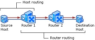
Host & Router Routing
Host Routing – Hosts actually use some simple routing logic when choosing where to send a packet. This two-step logic is as follows
- If destination IP address is in same subnet, send the packet directly to that destination host.
- If destination IP address is not in same subnet, send the packet to default gateway.
Router Routing – When a router gets a packet that is not destined for it, the router deliver it to either the destination host or to another router, as per the logic
- If destination network matches a router attached network, router forwards packet to destination by destination host’s physical address.
- If destination network is not directly attached, the router forwards packet to an intermediate router’s physical address chosen as per optimal route in the routing table.
DNS
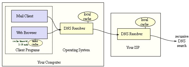
It is an Internet service to translate domain names into IP addresses as, domain names are alphabetic, they’re easy to remember but internet is based on IP addresses. A DNS service translates the name into the corresponding IP address like, the domain name www.example.com might translate to 198.105.232.4. The DNS system is an network as, if one DNS server doesn’t know how to translate a particular domain name, it asks another one, and so on, until the correct IP address is returned.
A DNS lookup can be bypassed by giving IP address instead of domain name. DNS works in an complex and hierarchical manner. After connecting the PC or network node to Internet service provider (ISP) or WiFi network, the modem or router assigns a network address to node and sends network configuration about one or more DNS servers to use.
DNS identifies by domain names that are organized as a tree or in hierarchical manner according to organizational or administrative boundaries. Each node of the tree, called a domain, is given a label. The domain name of the node is the concatenation of all the labels on the path from the node to the root node like network.support.vskills.in
- vskills.in is the domain name.
- . is the root domain
- in is the top level domain
- vskills is the second-level domain
- support is a subdomain of microsoft
- network is the hostname
For administrative purpose, domain name space is divided into DNS zones, each starting at a node and extending down to the leaf node or to nodes where other zones start. A DNS zone is a portion of the global DNS name space for which administrative responsibility has been delegated. The data for each zone is stored in a name server, which answers queries about the zone using the DNS protocol. A zone and a domain are different as a zone consists of discrete or contiguous portion of the domain tree, which can map exactly to a single domain or include only part of a domain. On the other hand, every node in the DNS tree is a domain, even if it has no subdomains. Any computer registered to join the Domain Name System can act as a DNS server. A DNS server contains a database of network names and address for other Internet hosts. DNS servers are organized in a hierarchy structure. At its top level, the root zone or root domain “.” is administered by a set of 13 root nameserver clusters distributed throughout the world. DNS protocol use both TCP and UDP ports — port 53/tcp and port 53/udp.
The Name Resolution process is done as
- Upon receiving query from client, the local nameserver will check if it has the authority for the required domain name. If it has, the local nameserver returns the IP address sought. Otherwise, go to step 2.
- Query one of the root nameservers to find the server authoritative for the next level down.
- Querying this second nameserver for the address of a DNS server with detailed knowledge of the second-level domain.
Repeating the previous step to progress down the name, until the final step which would, rather than generating the address of the next DNS server, return the final address sought.
DHCP
Dynamic Host Configuration Protocol (DHCP) is a network protocol to automatically assign an IP address and other network configuration to a computer from a defined range of numbers (i.e., a scope) configured for a given network. DHCP assigns an IP address when a system is started as
- A user turns on a computer with a DHCP client.
- The client computer sends a broadcast request (called a DISCOVER or DHCPDISCOVER), looking for a DHCP server to answer.
- The router directs the DISCOVER packet to the correct DHCP server.
- The server receives the DISCOVER packet. Based on availability and usage policies set on the server, the server determines an appropriate address (if any) to give to the client. The server then temporarily reserves that address for the client and sends back to the client an OFFER (or DHCPOFFER) packet, with that address information. The server also configures the client’s DNS servers, WINS servers, NTP servers, and sometimes other services as well.
- The client sends a REQUEST (or DHCPREQUEST) packet, letting the server know that it intends to use the address.
- The server sends an ACK (or DHCPACK) packet, confirming that the client has a been given a lease on the address for a server-specified period of time.
A computer is manually configured to use specified IP address but it can result in error or inattention to detail resulting in IP address conflict hence, DHCP is used. DHCP server uses three methods for allocating IP-addresses as
- Dynamic allocation- A range of IP addresses is assigned to DHCP server and each client requests an IP address from DHCP server for a lease with a controllable time period, allowing the DHCP server to reclaim (and then reallocate) IP addresses that are not renewed.
- Automatic allocation- The DHCP server permanently assigns a IP address to a requesting client from the range defined. But DHCP server keeps a table of past IP address assignments, so that it can preferentially assign to a client the same IP address that the client previously had.
- Static allocation- The DHCP server allocates an IP address based on a table with MAC address/IP address pairs, which are manually filled by administrator. It is not supported by all DHCP servers.
DHCP uses two ports destination UDP port 67 for sending data to the server, and UDP port 68 for data to the client. DHCP communications are connectionless in nature. DHCP clients and servers on the same subnet communicate via UDP broadcasts else for different subnets, a DHCP Helper or DHCP Relay Agent is used.
Internet
The World Wide Web (also called WWW or the Web), is a system of interlinked hypertext documents accessed via the Internet. With a web browser, user can view web pages with text, images, videos and other multimedia content, and navigate between them via hyperlinks. Hence, user can jump from one document to another simply by clicking on hot spots or hyperlinks. There are several applications called Web browsers that make it easy to access the World Wide Web like Mozilla Firefox, Google chrome and Microsoft’s Internet Explorer.
Web servers are computer systems with web server software running on them and having web sites or information in the form of web pages, which is accessible over internet.
User locates the server, the specific web page, and the protocol to get data from server by using DNS (getting server’s IP address from the server’s name) and HTTP (used for web page reply and request and hyper linking).
HTTP (Hyper Text Transfer Protocol), HTTPS & SSL
HyperText Transfer Protocol or HTTP is the protocol used by the World Wide Web and defined by RFC 2616. It specify message formatting and transmission with actions Web servers and browsers should take in response to various commands.
An HTTP session is a sequence of network request-response transactions. An HTTP client or user sends a request by establishing a Transmission Control Protocol (TCP) connection to a particular port on a server (port 80). An HTTP server listening on that port waits for a client’s request message. Upon receiving the request, the server sends back a status line, such as “HTTP/1.1 200 OK”, and a message of its own. The body of this message is typically the requested resource, although an error message or other information may also be returned.
HTTP defines several commands and responses and the most frequent the HTTP GET request with the filename, is sent from client to get a file from a web server. Server confirms by sending an HTTP GET response with a return code of 200 (meaning “OK”) and the file’s contents. HTML specifies Web pages formatting and display. HTTP is a stateless protocol. A stateless protocol does not require the HTTP server to retain information or status about each user for the duration of multiple requests. However, some web applications implement states or server side sessions using one or more of the following methods
- HTTP cookies.
- Query string parameters, for example, /index.php?session_id=some_unique_session_code.
- Hidden variables within web forms.
HTTPS
Hypertext Transfer Protocol Secure (HTTPS) is used for secure communication on Internet. It is layering addition of the HTTP on top of the SSL/TLS protocol, thus adding the security capabilities of SSL/TLS to standard HTTP communications. HTTPS provides authentication of the web site and associated web server communicating with. It provides bidirectional encryption of communications between a client and server. HTTPS encrypts the HTTP protocol including the request URL, query parameters, headers, and cookies.
Internet Terms (Hypertext, URL, Domain Name)
The World Wide Web (WWW) is a subset of the Net–a collection of interlinked documents that work together using a specific Internet protocol called Hypertext Transfer Protocol (HTTP). Web pages are written in Hypertext Markup Language (HTML), which tells the Web browser what to display. The significant feature of the Web is its ability to link pages to one another. Just click a link, and you’re at a Web site on the other side of the world hence, this moving around by clicking is called as ‘Surfing’.
Hypertext
Hypertext is text which contains links to other texts. Linking to objects whether text, pictures, music, programs, and so on can be creatively linked to each other. The hypertext pages are activated by a mouse click, key press sequence or by touching the screen.
URL
Uniform Resource Locator (URL) is the global address of documents and other resources on the World Wide Web. On the web, each web page has the URL which is in the address bar of browser as illustrated.

Some key parts to the URL are the protocol, the domain name and the file path.
Protocol – It is usually the “http”, followed by “://”, though it can be “https”, “ftp”, or other things. It is the method to get the information from a server. Web pages use the Hypertext Transfer Protocol (HTTP). It is the method how the information is given.
Hostname or Domain Name This is usually everything after “://” but before the next “/”, if there is one. It is usually the domain name. A hostname like “www.example.com” can be further broken down into the top-level domain (“com”), the domain name (“example.com”), and the sub domain (“www”). It is also called the host address and can also be a number called an IP address. All computers on Internet have an IP address which is a set of 12 digits separated by a period. A domain name is converted into IP address for getting the web page by a domain name server (DNS), which has directory of domain names and the corresponding IP addresses.
An organization can register for a domain name, selecting one of the top-level specifications mentioned above that describes it best, and then preceding it with a recognizable version of its name. For example, the ABC Software Systems company will have a domain name like abc.com. From there, it can divide itself into sub domains, extending the organization chart to department levels, or it can just give all of its computers names in the abc.com domain.
File Path – It is anything that appears after the “/” or after the hostname, but before a possible “?”. An example would be “games/images/display.html”. It can be quite long. It can have a filename (“display.html” in the previous example), or just be one or more directories (“games/images/” in that example). This denotes what file to display at that site. It always begins with a forward slash character and may consist of one or more directory names. It usually correspond to the directory structure of the web site
Every file on the Web has its URL to be accessed by web server and if a file has no URL, the web server will then
- Look for a default file and return that like index.html.
- Show a error message saying that the page cannot be found or a 404 message.
ISP (Internet Service Provider)
An ISP (Internet Service Provider) is a company which provides internet access to other companies or individuals. An ISP maintains connections to other networks and ISPs, acting as a router for internet traffic between a customer’s computer and any other machine also connected to the internet anywhere else in the world.
Web Browser
It is application software, which is used to locate, retrieve and also display content on the World Wide Web, including Web pages, images, video and other files. As a client/server model, the browser is the client run on a computer that contacts the Web server and requests information. The Web server sends the information back to the Web browser which displays the results on the computer or other Internet-enabled device that supports a browser.
Today’s browsers are fully-functional software which interpret and display HTML and HTML 5 Web pages, applications, JavaScript, AJAX and other content hosted on Web servers. Many browsers offer plug-ins which extends the capabilities of a browser like the flash plug-in.
Commonly used browsers are Mozilla Firefox from Mozilla Foundation with the latest release is version 21 and Internet Explorer from Microsoft and the latest release is version 11. Other major browsers include Google Chrome, Apple Safari and Opera.
A number of browsers are used to access the Web on a mobile device. These mobile browsers ( also called as “Microbrowser”) are optimized to display Web content on smaller mobile device screens and to also perform using less computing power and memory capacity compared to a desktop or laptop computers. Mobile browsers are typically “stripped down” versions of Web browsers and offer fewer features in order to run well on mobile devices.
Virtual Private Networks (VPN)
It is the extension of a private network having links across shared or public networks like the Internet. It enables data transfer between two nodes across a shared or public network in a manner that emulates the properties of a point-to-point private link by encapsulating or wrapping with a header that provides routing information allowing it to traverse the shared or public network and encrypted for confidentiality to make data indecipherable if intercepted. It uses the encryption keys. The part of VPN connection in which the private data is encapsulated is known as the tunnel. The portion of the connection in which the private data is encrypted is known as the virtual private network (VPN) connection.
VPN connects users to a remote network or connect multiple networks together or access resources on remote networks. VPN users get the impression of being directly connected to the central network via a point-to-point link. They are classified as
- the protocols used to tunnel the traffic
- the tunnel’s termination point, i.e., customer edge or network-provider edge
- whether they offer site-to-site or remote-access connectivity
- the levels of security provided
- the OSI layer they present to the connecting network, like layer 2 or 3
VPN uses following protocols for security
- IPSec (Internet Protocol Security) was developed by the Internet Engineering Task Force (IETF), and was initially developed for IPv6, which requires it. This standards-based security protocol is also widely used with IPv4. Layer 2 Tunneling Protocol frequently runs over IPSec. Its design meets most security goals of authentication, integrity, and confidentiality. IPSec functions through encrypting and encapsulating an IP packet inside an IPSec packet. De-encapsulation happens at the end of the tunnel, where the original IP packet is decrypted and forwarded to its intended destination.
- Transport Layer Security (SSL/TLS) can tunnel an entire network’s traffic, as it does in the OpenVPN project, or secure an individual connection. A number of vendors provide remote access VPN capabilities through SSL. An SSL VPN can connect from locations where IPsec runs into trouble with Network Address Translation and firewall rules.
- Secure Shell (SSH) VPN – OpenSSH offers VPN tunneling (distinct from port forwarding) to secure remote connections to a network or inter-network links. OpenSSH server provides a limited number of concurrent tunnels and the VPN feature itself does not support personal authentication.
Firewalls
A firewall is used to help keep a network secure by controlling the incoming and outgoing network traffic after analyzing the data packets and determining whether it should be allowed through or not, based on a predetermined rule set. It can either be software-based or hardware-based and it acts as a bridge between an internal network which is assumed secure and trusted, and another network, usually an external (inter)network, such as the Internet, that is not assumed to be secure and trusted. Many personal computer operating systems include software-based firewalls to protect against threats from the public Internet. Many routers that pass data between networks contain firewall components and, conversely, many firewalls can perform basic routing functions. Various criteria are used by firewall for data filtering as
- IP address — a firewall can block all traffic to or from a certain IP address.
- Domain names — a firewall can block all access to certain domain names, or allow access only to specific domain names.
- Protocols — a firewall may set up a few hosts to handle a specific protocol and ban that protocol on other hosts.
- Ports — a firewall can block the access of certain ports on all the hosts inside the LAN.
The level of security setting for the firewall is based on security threats to be addressed as higher security level usually limits internet connectivity. There are several types of firewall techniques as
- Packet filter – Looks at each packet entering or leaving the network and accepts or rejects it based on user-defined rules. Packet filtering is fairly effective and transparent to users, but it is difficult to configure. In addition, it is susceptible to IP spoofing.
- Application gateway – Applies security mechanisms to specific applications, such as FTP and Telnet servers. This is very effective, but can impose a performance degradation.
- Circuit-level gateway – Applies security mechanisms when a TCP or UDP connection is established. Once the connection has been made, packets can flow between the hosts without further checking.
- Proxy server – Intercepts all messages entering and leaving the network. The proxy server effectively hides the true network addresses.
Firewalls also use a DMZ (demilitarized zone), which is a computer host or small network inserted as a “neutral zone” between a company’s private network and the outside public network. It prevents outside users from getting direct access to a server that has company data.
