If you are going to create a two dimensional drawing that has one view, you can create the drawing and its annotation entirely in model space. This is the traditional method for creating drawings with AutoCAD®.
Model Space Drafting
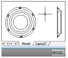
The process of creating and plotting a drawing file in model space is very different from the process used in manual drafting. In AutoCAD, there are two distinct working environments that are represented by the Model and layout tabs. These tabs are located near the bottom of the drawing area.
If you are going to create a two-dimensional drawing that has one view, you can create both the model and its annotation entirely in model space, not using a layout tab. This is the traditional method for creating drawings with AutoCAD. This method is simple but has several limitations, including
- It is suitable for 2D drawings only
- It does not support multiple views and view-dependent layer settings
- Scaling the annotation and title block requires computation unless you use annotative objects.
With this method, you always draw geometric objects at full scale (1:1) and text, dimensions, and other annotation at a scale that will appear at the correct size when the drawing is plotted.
Model Tab
The Model tab accesses a limitless drawing area called model space. In model space, you draw, view, and edit your model.
In model space, you draw your model at 1:1 scale, and you decide whether one unit represents one millimeter, one centimeter, one inch, one foot, or whatever unit is most convenient or customary in your business. On the Model tab, you can view and edit model space objects. The crosshairs cursor is active over the entire drawing area. In model space, you can also define named views that you display in layout viewports on a layout.
Model Space Operations
If you draw and plot from model space, you must determine and apply a scale factor to annotate objects before you plot. You can draw and plot entirely from model space. This method is useful primarily for two-dimensional drawings that have a single view. With this method, you use the following process.
- Determine the unit of measurement (drawing units) for the drawing.
- Specify the display style for the drawing unit.
- Calculate and set the scale for dimensions, annotations, and blocks.
- Draw at full scale (1:1) in model space.
- Create the annotation and insert the blocks in model space.
- Plot the drawing at the predetermined scale.
You can also use annotative objects if you want to scale annotations automatically.
Determine the Unit of Measurement – Before you begin drawing in model space, you determine the unit of measurement (drawing units) that you plan to use. You decide what each unit on the screen represents, such as an inch, a millimeter, a kilometer, or some other unit of measurement. For example, if you are drawing a motor part, you might decide that one drawing unit equals a millimeter. If you are drawing a map, you might decide that one unit equals a kilometer.
Specify the Display Style of Drawing Units – Once you have determined a drawing unit for the drawing, you need to specify the style for displaying the drawing unit, which includes the unit type and precision. For example, a value of 14.5 can be displayed as 14.500, 14-1/2, or 1’2-1/2″.
Specify the display style of drawing units with the UNITS command. The default drawing unit type is decimal.
Set the Scale for Annotations and Blocks – Before you draw, you should set the scale for dimensions, annotations, and blocks in your drawings. Scaling these elements beforehand ensures that they are at the correct size when you plot the final drawing. You should enter the scale for the following objects
- Set the text height as you create text or by setting a fixed text height in the text style ( STYLE).
- Set the dimension scale in a dimension style ( DIMSTYLE) or with the DIMSCALE system variable.
- Set the scale for noncontinuous linetypes with the CELTSCALE and LTSCALE system variables.
- Hatch patterns. Set the scale for hatch patterns in the Hatch and Gradient dialog box ( HATCH) or with the HPSCALE system variable.
- Specify the insertion scale for blocks either as you insert them, or set an insertion scale in the Insert dialog box ( INSERT) or in DesignCenter ( ADCENTER). The system variables used for inserting blocks are INSUNITS, INSUNITSDEFSOURCE, and INSUNITSDEFTARGET. This also applies to the border and title block of the drawing.
You can also use annotative objects if you want to scale annotations automatically.
Determine the Scale Factor for Plotting – To plot your drawing from the Model tab, you calculate the exact scale factor by converting the drawing scale to a ratio of 1:n. This ratio compares plotted units to drawing units that represent the actual size of the objects you are drawing.
For example, if you plan to plot at a scale of 1/4 inch = 1 foot, you would calculate the scale factor 48 as follows:
1/4″ = 12″
1 = 12 x 4
1 (plotted unit) = 48 (drawing units)
Using the same calculation, the scale factor for 1 centimeter = 1 meter is 100, and the scale factor for 1 inch = 20 feet is 240.
Sample Scale Ratios – The sample architectural scale ratios in the table can be used to calculate text sizes in model space.
| Scale | Scale factor | To plot text size at | Set drawing text size to |
| 1 cm = 1 m | 100 | 3 mm | 30 cm |
| 1/8″ = 1′-0″ | 96 | 1/8″ | 12″ |
| 3/16″ = 1′-0″ | 64 | 1/8″ | 8″ |
| 1/4″ = 1′-0″ | 48 | 1/8″ | 6″ |
| 3/8″ = 1′-0″ | 32 | 1/8″ | 4″ |
| 1/2″ = 1′-0″ | 24 | 1/8″ | 3″ |
| 3/4″ = 1′-0″ | 16 | 1/8″ | 2″ |
| 1″ = 1′-0″ | 12 | 1/8″ | 1.5″ |
| 1 1/2″ = 1′-0″ | 8 | 1/8″ | 1.0″ |
If you are working in metric units, you might have a sheet size of 210 x 297 mm (A4 size) and a scale factor of 20. You calculate grid limits as
210 x 20 = 4200 mm
297 x 20 = 5900 mm
To specify the display style for drawing units
- Click Format menu
- In the Drawing Units dialog box, set the unit values for your drawing.
- As you change unit settings, you can see examples under Sample Output.
- Under Length, select a unit type and level of precision. This determines the display style for linear drawing units.
- Under Drawing Units for DesignCenter Blocks, select the unit that you want used to scale blocks, images, or other content inserted into the drawing. If you do not want inserted content to be scaled, select Unitless.
- Under Angle, select an angle type and precision. This determines the display style for angular drawing units. The default starting angle, 0 degrees, is toward 3 o’clock (or east).
- To specify an angle direction, click Direction, and then select the base angle in the Direction Control dialog box. The angle direction controls the point from which angles are measured and the direction in which they are measured. If you select Other, you can enter an angle, or click Angle to specify an angle using your pointing device. The default positive angle measurement is counterclockwise.
- Click OK to exit each dialog box.
