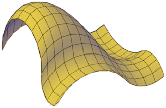
Mesh tessellation provides enhanced capabilities for modeling object shapes in a more detailed way.
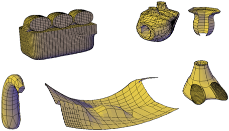
Starting with AutoCAD 2010, the default mesh object type can be smoothed, creased, split, and refined. Although you can continue to create the legacy polyface and polygon mesh types, you can obtain more predictable results by converting to the newer mesh object type.
Methods for Creating Mesh
You can create mesh objects using the following methods:
- Create mesh primitives. Create standard shapes, such as boxes, cones, cylinders, pyramids, spheres, wedges, and tori ( MESH).
- Create mesh from other objects. Create ruled, tabulated, revolved, or edge-defined mesh objects, whose boundaries are interpolated from other objects or points ( RULESURF, TABSURF, REVSURF, EDGESURF).
- Convert from other object types. Convert existing solid or surface models, including composite models, to mesh objects ( MESHSMOOTH). You can also convert the legacy style of mesh to the new mesh object type.
- Create custom meshes (legacy). Use 3DMESH to create polygon meshes, usually scripted with AutoLISP routines, to create open-ended mesh. Use PFACE to create mesh with multiple vertices defined by coordinates that you specify. Although you can continue to create legacy polygonal and polyface meshes, it is recommended that you convert to the enhanced mesh object type to obtain enhanced editing capabilities.
About Tessellation
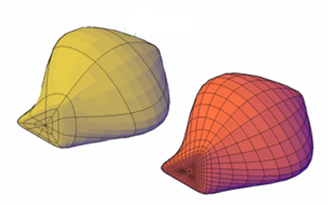
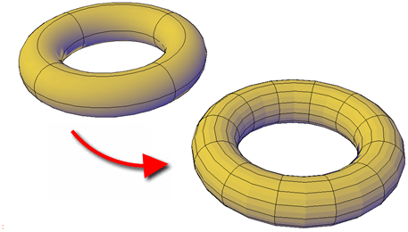
Tessellation is a collection of planar shapes that tile a mesh object. The tessellation divisions, visible in unselected mesh objects, mark the edges of the editable mesh faces. (To see these divisions in the 3D Hidden or Conceptual visual styles, VSEDGES must be set to 1.) When you smooth and refine mesh objects, you increase the density of the tessellation (the number of subdivisions).
- Smoothing. Increases how closely the mesh surface adheres to a rounded form. You can increase mesh smoothness levels for selected objects in increments or by changing the smoothness level in the Properties palette. Smoothness level 0 (zero) applies the lowest level of smoothing to a mesh object. Smoothness level 4 applies a high degree of smoothness.
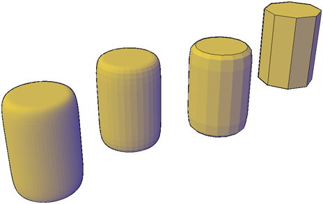
- Quadruples the number of subdivisions in a selected mesh object or in a selected subobject, such as a face. Refinement also resets the current smoothness level to 0, so that the object can no longer be sharpened beyond that level. Because refinement greatly increases the density of a mesh, you might want to restrict this option to areas that require finely detailed modification. Refinement also helps you mold smaller sections with less effect on the overall shape of the model.
While highly refined mesh gives you the ability to make detailed modifications, it also comes at a cost: it can decrease program performance. By maintaining maximum smoothness, face, and grid levels, you can help ensure that you do not create meshes that are too dense to modify effectively. (Use SMOOTHMESHMAXLEV, SMOOTHMESHMAXFACE, and SMOOTHMESHGRID.)
Set Mesh Properties Before and After Creation
You can set defaults that control a variety of mesh properties before and after you create the mesh objects.
- Mesh Primitive Options dialog box. Sets the density of the tessellation (the number of subdivisions) per dimension for each type of mesh object you create.
- Mesh Tessellation Options dialog box. Sets the default settings for 3D solid or surface objects that you convert to mesh. Options define how closely mesh faces adhere to the shape of the object and level of smoothness. You can also set the default to prefer the settings in the Mesh Primitive Options dialog box for object conversions.
- Properties palette. Modifies properties for both the mesh object and its subobjects after they are created. For a selected mesh object, you can modify the level of smoothness. For faces and edges, you can apply or remove creasing, and modify crease retention levels.
Level of smoothness. By default, the mesh primitive objects that you create have no smoothness. You can change this default with the Settings option of the MESH command. The modified smoothness value is maintained only during the current drawing session.
Mesh Box
The base of the mesh box is drawn parallel to the XY plane of the current UCS (workplane). You can set defaults for the number of divisions for each dimension of new mesh boxes in the Mesh Primitive Options dialog box. You can also modify these settings and the level of smoothness as you create the mesh object.
The Box option of the MESH command provides several methods for determining the size and rotation of the mesh boxes you create.
- Create a cube. Use the Cube option to create a mesh box with sides of equal length.
- Specify rotation. Use the Cube or Length option if you want to set the rotation of the box in the XY plane.
- Start from the center point. Use the Center option to create a box using a specified center point.
Mesh Cone
Create a pointed or frustum mesh cone with a circular or elliptical base.
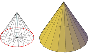
By default, the base of the mesh cone lies on the XY plane of the current UCS and the height of the cone is parallel to the Z axis. You can set the number of divisions for each dimension of new mesh cones in the Mesh Primitive Options dialog box. You can also modify these settings and the level of smoothness as you create the mesh object.
The Cone option of the MESH command provides several methods for determining the size and rotation of the mesh cones you create.
- Set the height and orientation. Use the Axis Endpoint option when you want to reorient the cone by placing the tip or axis endpoint anywhere in 3D space.
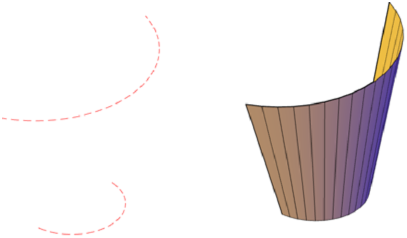
- Create a frustum of a cone. Use the Top Radius option to create a frustum of a cone, which tapers to an elliptical or planar face.
- Specify circumference and base plane. The 3P (Three Points) option defines the size and plane of the base of the cone anywhere in 3D space.
- Create an elliptical base. Use the Elliptical option to create a cone base whose axes are different lengths.
- Set the location to be tangent to two objects. Use the Ttr (Tangent, Tangent, Radius) option to define points on two objects. Depending on the radius distance, the new cone is located as near as possible to the tangent points you specify. You can set up tangency with circles, arcs, lines, and some 3D objects. The tangency points are projected onto the current UCS. The appearance of tangency is affected by the current level of smoothness.
Meshes from Other Objects
Create mesh forms by filling the space between other objects such as lines and arcs. You can use a variety of methods to create mesh objects whose edges are defined by other objects. The MESHTYPE system variable controls whether the new objects are valid mesh objects, or whether they are created using legacy polyface or polygon geometry. You can control whether the mesh is displayed as a wireframe, hidden, or conceptual image by changing the visual style ( VISUALSTYLES). You can create several types of meshes that are based on existing objects.
Ruled mesh. RULESURF creates a mesh that represents the ruled surface between two lines or curves.
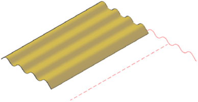
Tabulated mesh. TABSURF creates a mesh that represents a general tabulated surface. The surface is defined by the extrusion of a line or curve (called a path curve) in a specified direction and distance (called a direction vector or path).
Revolved mesh. REVSURF creates a mesh that approximates a surface of revolution by rotating a profile about a specified axis. A profile can consist of lines, circles, arcs, ellipses, elliptical arcs, polylines, splines, closed polylines, polygons, closed splines, and donuts.
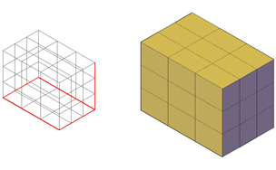
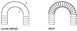
Edge-defined mesh. EDGESURF creates a mesh approximating a Coons surface patch mesh from four adjoining edges. A Coons surface patch mesh is a bicubic surface that is interpolated between four adjoining edges (which can be general space curves).
Create a Ruled Mesh – There are several methods for creating meshes.
With RULESURF, you create a mesh between two lines or curves. Use two different objects to define the edges of the ruled mesh: lines, points, arcs, circles, ellipses, elliptical arcs, 2D polylines, 3D polylines, or splines. Both objects that are used as the “rails” of a ruled mesh must be either open or closed. You can pair a point object with either an open or a closed object.
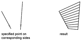
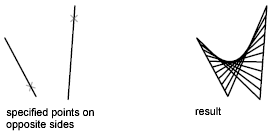
You can specify any two points on closed curves to complete the operation. For open curves, construction of the ruled mesh is based on the locations of the specified points on the curves.
Mesh by Conversion
Convert solids, surfaces, and legacy mesh types to mesh objects. You can use the MESHSMOOTH command to convert certain objects to mesh. Convert 3D solids, surfaces, and legacy mesh objects to the enhanced mesh object in order to take advantage of capabilities such as smoothing, refinement, creasing, and splitting.
You obtain the most predictable results when you convert primitive solid objects to mesh. That is, the resulting mesh adheres closely to the shape of the original solid model. You can also convert other types of objects, although the conversion results may differ from what you expect. These objects include swept surfaces and solids, legacy polygon and polyface mesh objects, regions, closed polylines, and objects created with 3DFACE. For these objects, you can often improve results by adjusting the conversion settings.
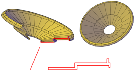
Adjust Mesh Conversion Settings – If the conversion does not work as expected, try changing the settings in the Mesh Tessellation Options dialog box. For example, if the Smooth Mesh Optimized mesh type results in incorrect conversions, you can set the tessellation shape to be Triangle or Mostly Quads.
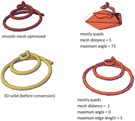
You also can control the adherence to the original shape by setting the maximum distance offset, angles, aspect ratios, and edge lengths for new faces. The following example shows a 3D solid helix that has been converted to mesh using different tessellation settings. The optimized mesh version has been smoothed, but the other two conversions have no smoothness. Notice, however, that the mostly quads conversion with the lower tessellation values creates a mesh object that adheres most closely to the original version. Smoothing this object improves its appearance even more.
Similarly, if you notice that a converted mesh object has a number of long, slivered faces (which can sometimes cause gaps), try decreasing the Maximum Edge Length for New Faces value.
If you are converting primitive solid objects, this dialog box also offers the option of using the same default settings used to create primitive mesh objects.
