Three-dimensional solid objects often start as one of several basic shapes, or primitives, that you can then modify and recombine. A 3D solid or surface can also be the result of extruding a 2D shape to follow a specified path in 3D space.
Solid Primitives
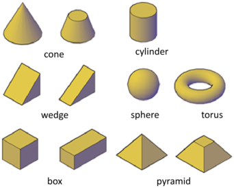
You can create several basic 3D shapes, known as solid primitives: boxes, cones, cylinders, spheres, wedges, pyramids, and tori (donuts).
By combining primitive shapes, you can create more complex solids. For example, you can join two solids, subtract one from the other, or create a shape based on the intersection of their volumes.
Solids Based on Other Objects
You can also create 3D solids and surfaces from existing objects.
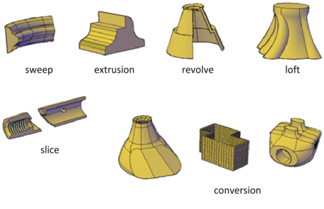
The following methods are available
- Extends a 2D object along a path.
- Extends the shape of a 2D object in a perpendicular direction into 3D space.
- Sweeps a 2D object around an axis.
- Extends the contours of a shape between one or more open or closed objects.
- Divides a solid object into two separate 3D objects.
- Converts mesh objects and planar objects with thickness into solids and surfaces.
Visual Styles
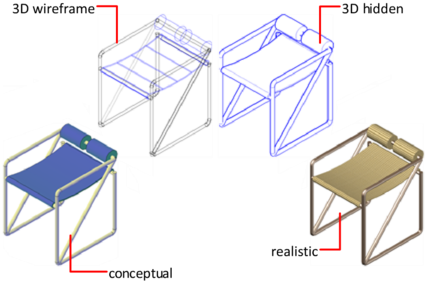
Solids and surfaces can be displayed in one of several visual styles that are applied to the viewport.
Solid Box
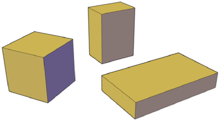
The base of the box is always drawn parallel to the XY plane of the current UCS (workplane). Use the following options to control the size and rotation of the boxes you create
- Create a cube. Use the Cube option of the BOX command to create a box with sides of equal length.
- Specify rotation. Use the Cube or Length option if you want to set the rotation of the box in the XY plane.
- Start from the center point. Use the Center Point option to create a box using a specified center point.
Solid Wedge
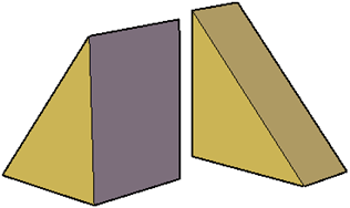
The base of the wedge is drawn parallel to the XY plane of the current UCS with the sloped face opposite the first corner. The height of the wedge is parallel to the Z axis. Use the following options to control the size and rotation of the wedges you create
- Create a wedge with sides of equal length. Use the Cube option of the WEDGE command.
- Specify rotation. Use the Cube or Length option if you want to set the rotation of the wedge in the XY plane.
- Start from the center point. Use the Center Point option to create a wedge using a specified center point.
Solid Cone
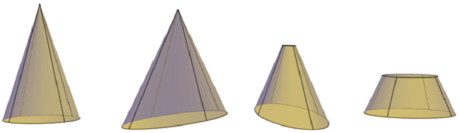
By default, the base of the cone lies on the XY plane of the current UCS. The height of the cone is parallel to the Z axis. Use the following options to control the size and rotation of the cones you create
- Set the height and orientation. Use the Axis Endpoint option of the CONE command. Use the Top Radius option to specify the axis endpoint as the point of the cone or the center of the top face. The axis endpoint can be located anywhere in 3D space.
- Create a frustum of a cone. Use the Top Radius option of the CONE command to create a frustum, which tapers to an elliptical or planar face.
- The Frustum tool is also available from the Modeling tab of the tool palette. You can also use grips to modify the tip of a cone and convert it to a flat face.
- Specify circumference and base plane. The 3P (Three Points) option of the CONE command defines the size and plane of the base of the cone anywhere in 3D space.
- Define the angle of the taper. To create a conical solid that requires a specific angle to define its sides, draw a 2D circle. Then use EXTRUDE and the Taper Angle option to taper the circle at an angle along the Z axis. This method, however, creates an extruded solid, not a true solid cone primitive.
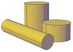
Solid Cylinder
By default, the base of the cylinder lies on the XY plane of the current UCS. The height of the cylinder is parallel to the Z axis. Use the following options to control the size and rotation of the cylinders you create
- Set rotation: Use the Axis Endpoint option of the CYLINDER command to set the height and rotation of the cylinder. The center point of the top plane of the cylinder is the axis endpoint, which can be located anywhere in 3D space.
- Use three points to define the base. Use the 3P (Three Points) option to define the base of the cylinder. You can set three points anywhere in 3D space.
- Construct a cylindrical form with special detail, such as grooves. Create a closed polyline ( PLINE to represent a 2D profile of the base. Use EXTRUDE to define the height along the Z axis. The resulting extruded solid is not a true solid cylinder primitive.
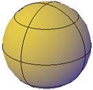
Solid Sphere
When you start with the center point, the central axis of the sphere parallels the Z axis of the current user coordinate system (UCS). Use the following options to draw a sphere with the SPHERE command
- Specify three points to set the size and plane of the circumference or radius. Use the 3P (Three Points) option to define the size of the sphere anywhere in 3D space. The three points also define the plane of the circumference.
- Specify two points to set the circumference or radius. Use the 2P (Two Points) option to define the size of the sphere anywhere in 3D space. The plane of the circumference matches the Z value of the first point.
- Set the size and location of the sphere based on other objects. Use the Ttr (Tangent, Tangent, Radius) option to define a sphere that is tangent to two circles, arcs, lines, and some 3D objects. The tangency points are projected onto the current UCS.
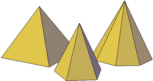
Solid Pyramid
You can create a pyramid that tapers to a point, or create a frustum of a pyramid, which tapers to a planar face. Use the following options to control the size, shape, and rotation of the pyramids you create
- Set the number of sides. Use the Sides option of the PYRAMID command to set the number of sides for the pyramid.
- Set the length of the edges. Use the Edges option to specify the dimension of the sides at the base.
- Create a frustum of a pyramid. Use the Top Radius option to create a frustum, which tapers to a planar face. The frustum face is parallel to, and has the same number of sides as, the base.
- Set the height and rotation of the pyramid. Use the Axis Endpoint option of the PYRAMID command to specify the height and rotation of the pyramid. This endpoint, or top of the pyramid, can be located anywhere in 3D space.
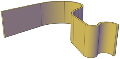
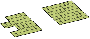
Polysolid
Use the same techniques you use to create polylines to create a polysolid object.
The POLYSOLID command provides a quick way to draw 3D walls. A polysolid is like an extruded, wide polyline. In fact, you can draw polysolids the same way that you draw a polyline, using both straight and curved segments. Unlike extruded polylines, which lose any width properties upon extrusion, polysolids retain the width of their line segments. You can also convert objects such as a line, 2D polyline, arc, or circle to a polysolid.
Extrude Objects
Create solids and surfaces by extending objects into 3D space.
The EXTRUDE command creates a solid or surface that extends the shape of an object. Closed objects such as circles are converted to 3D solids. Open objects such as lines are converted to 3D surfaces.
If you extrude a polyline with width, the width is ignored and the polyline is extruded from the center of the polyline path. If you extrude an object with thickness, the thickness is ignored.
Before you can create an extruded solid from separate objects such as multiple lines or arcs, you must convert them to a single object. You can combine objects to form a polyline by using the Join option of the PEDIT command. You can also convert the objects to form a region by using the REGION command.
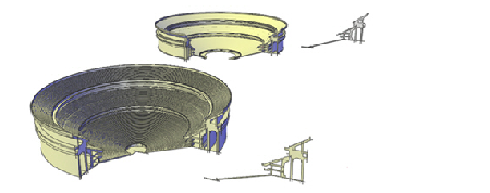
Sweeping
Create a new solid or surface by sweeping a planar curve (profile) along a path. The SWEEP command draws a solid or surface object by extending a profile shape (the swept object) along a specified path. When you sweep a profile along a path, the profile is moved and aligned normal (perpendicular) to the path. If you sweep a closed curve along a path, the result is a solid. If you sweep an open curve along a path, the result is a surface.
You can sweep more than one profile object, but all objects must lie on the same plane.
The DELOBJ system variable controls whether the profile and sweep path are automatically deleted.
Swept objects can be twisted or scaled as they are swept. You can also use the Properties palette to specify the following properties for the swept object
- Profile Rotation. Rotates the swept profile about the path.
- Scale Along Path. Sets a scale factor of the end of the profile compared to the start of the profile.
- Twist Along Path. Sets a twist angle for the objects being swept. The value you enter sets the angle of rotation of the endpoint compared to the start point.
- Bank (natural rotation). Specifies whether the curve of a twisted profile rotates naturally along a 3D path.
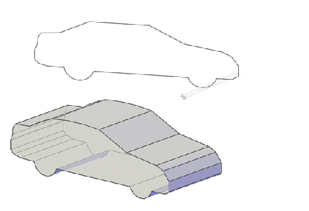
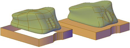
Lofting
Create a 3D solid or surface by lofting a profile through a set of two or more cross-section profiles. The cross-section profiles define the shape of the resulting solid or surface object. You must specify at least two cross-section profiles.
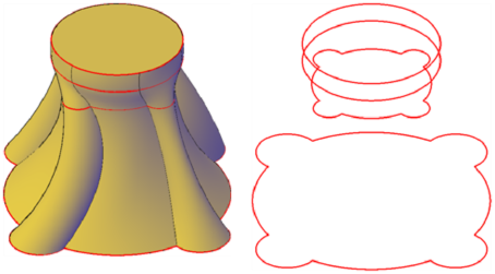
Cross-section profiles can be open (for example, an arc) or closed (for example, a circle). The LOFT command flows through the space between the cross sections. If you loft through a set of a closed cross-section curves, the result is a solid object. If you loft through a set of open cross-section curves, the result is a surface object.
The cross sections that you use when lofting must be all open or all closed. You cannot use a selection set that includes both open and closed curves. The DELOBJ system variable controls whether the cross sections, paths, and guides are automatically deleted when the solid or surface is created.
Lofting creates a solid or surface object that flows through other objects that define its shape. Cross-section profiles. Select a series of cross-section profiles to define the shape of the new 3D object. Lofted objects with different cross-section settings.
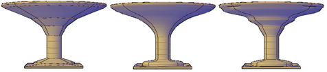
As you create a lofted object using only cross-section profiles, you can adjust its shape in the Loft Settings dialog box. You can also modify the settings later in the Properties dialog box. For more information, see Modify Properties of 3D Objects
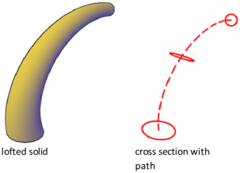
Paths: Specify a path for the loft operation to obtain more control over the shape of the lofted object. For best results, start the path curve on the plane of the first cross section and end it on the plane of the last cross section.
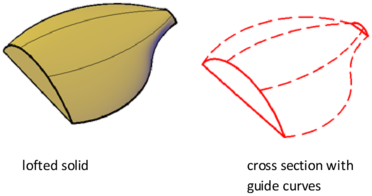
Guide Curves: Specify guide curves to match points on corresponding cross sections. This method prevents undesired results, such as wrinkles in the resulting 3D object.
Revolving: With the REVOLVE command, you can revolve open or closed objects about an axis. The revolved objects define the profile of the new solid or surface.
If you revolve a closed object, the result is a solid. If you revolve an open object, the result is a surface. You can revolve more than one object at a time.
Methods for Creating a Revolved Solid or Surface – When you revolve objects, you can specify one of the following options to use as an axis of revolution:
- Axis defined by two points you specify
- X, Y, or Z axis
- Axis defined by an object
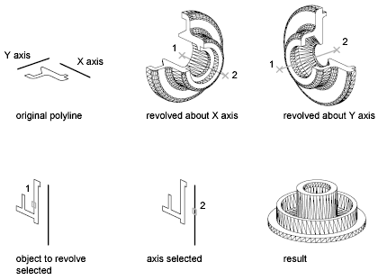
A profile that consists of lines or arcs that meet a polyline creates a surface object when it is revolved. To create a 3D solid object instead, first convert the profile objects to a single polyline by using the Join option of the PEDIT command.
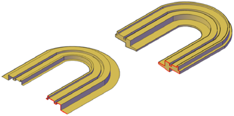
3D Solids from Objects
You can use several methods to convert objects in your drawing to 3D solids. Mesh and polyline with thickness converted to optimized 3D solids.
The DELOBJ system variable controls whether the objects you select are automatically deleted when the 3D object is created.
Convert Surfaces and Objects with Thickness to 3D Solids
You can convert the several types of objects into extruded 3D solids with the CONVTOSOLID command. These objects include closed polylines and circles with thickness, as well as watertight meshes and surfaces. For a complete list of objects that can be converted using this method, see CONVTOSOLID.
NoteYou cannot use CONVTOSOLID to convert different, contiguous objects into a 3D solid. However, you can achieve the same result by first combining them. Suppose you explode a 3D solid box into regions. Start by using CONVTOSURFACE to convert each region to a surface. Then use UNION to form a compound surface object. Finally, use CONVTOSOLID to convert the surface to a solid.
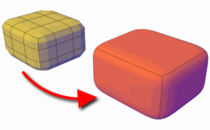
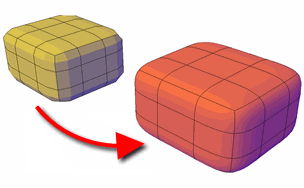
Convert Mesh to 3D Solids
When you convert mesh objects to 3D solids, the shape of the new solid object approximates, but does not exactly duplicate, the original mesh object. You can control the differentiation somewhat by specifying whether the result is smooth or faceted ( SMOOTHMESHCONVERT). You can also specify whether the resulting faces are merged (optimized). For example, if you convert a mesh box to a solid object, you have the following options (available on the Mesh Modeling ribbon):
Smoothed and optimized. Coplanar faces are merged into a single face. The overall shape of some faces can change. Edges of faces that are not coplanar are rounded.
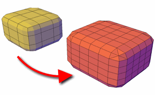
Smoothed and not optimized. Each original mesh face is retained in the converted object. Edges of faces that are not coplanar are rounded.
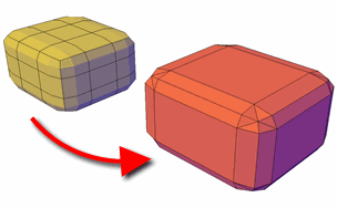
Faceted and optimized: Coplanar faces are merged into a single, flat face. The overall shape of some faces can change. Edges of faces that are not coplanar are creased, or angular.
Faceted and not optimized: Each original mesh face is converted to a flat face. Edges of faces that are not coplanar are creased, or angular.
You cannot convert the following types of mesh objects to a 3D solid:
- Mesh with gaps between faces. Gizmo editing can sometimes result in gaps, or holes between the faces. In some cases, you can close the gaps by smoothing the mesh object.
- Mesh that has self-intersecting boundaries. If you have modified a mesh object so that one or more faces intersect faces in the same object, you cannot convert it to a 3D solid.
- In some cases, mesh that is not eligible to be converted to a solid object can be converted to a surface.
Surfaces from Objects
You can use several methods to convert objects in your drawing to 3D surfaces.
The DELOBJ system variable controls whether the objects you select are automatically deleted when the 3D object is created.
Convert Objects to Surfaces
To convert any of the following objects into surfaces, use the CONVTOSURFACE command:
- 2D solids
- Meshes
- Regions
- Bodies
- Open, zero-width polylines with thickness
- Lines with thickness
- Arcs with thickness
- Planar 3D faces
You can also create surfaces from 3D solids that have curved faces by exploding them. To convert objects such as cylinders, use the EXPLODE command. When you convert mesh objects to surfaces, the shape of the new solid object approximates, but does not exactly duplicate, the original mesh object. You can control the differentiation somewhat by specifying whether the result is smooth or faceted ( SMOOTHMESHCONVERT). You can also specify whether the resulting faces are merged (optimized).
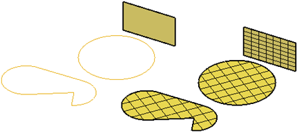
Create a Planar Surface – Create a flat, planar surface, use the PLANESURF command. You can use either of the following options
- Select one or more objects that form one or more enclosed areas
- Specify the opposite corners of a rectangle
When you specify the corners of the surface, the surface is created parallel to the workplane.
Composite Objects
Create composite 3D objects by combining, subtracting, or finding the intersecting mass of two or more 3D solids, surfaces, or regions. Composite solids are created from two or more solids, surfaces, or regions through any of the following commands: UNION, SUBTRACT, and INTERSECT.
By default, 3D solids record a history of their original forms. This history allows you to see the original forms that make up composite solids. Surface objects do not retain history.
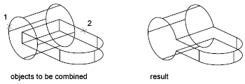
Methods for Creating Composite Objects – Three methods are available for creating composite solids, surfaces, or regions:
Combine two or more objects – With UNION, you can combine the total volume of two or more objects.
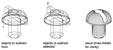
Subtract one set of solids from another – With SUBTRACT, you can remove the common area of one set of solids from another. For example, you can use SUBTRACT to add holes to a mechanical part by subtracting cylinders from the object.
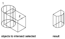
Find the common volume – With INTERSECT, you can create a composite solid from the common volume of two or more overlapping solids. INTERSECT removes the portions that do not overlap and creates a composite solid from the common volume.
Create Composites from Mixed Object Types – In addition to creating composite objects from the same object types, you can also create composites from mixed surfaces and solids.
- Mixed intersections. Combining a solid and surface through intersection results in a surface.
- Mixed subtractions. Subtracting a 3D solid from a surface results in a surface. However, you cannot subtract a surface from a 3D solid object.
- Mixed unions. You cannot create a union between 3D solid and surface objects.
If a selection set contains objects that are both eligible and ineligible to be composite objects, the ineligible objects are ignored. For example, with the SUBTRACT command, if you select a solid object to be modified and then select both a solid and a surface to be subtracted, only the solid object is subtracted.
3D Solids or Surfaces by Slicing
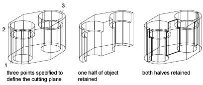
Create new 3D solids or surfaces by slicing, or dividing, existing objects. When you use the SLICE command to slice a 3D solid or surface, you can define the cutting plane in several ways. For example, you can specify three points, an axis, a surface, or a planar object to act as a cutting plane. You can retain one or both halves of the sliced object.
Sliced 3D solids do not retain a history of the original forms that created them. However, they do retain the layer and color properties of the original objects.
Methods for Slicing 3D Solids
- You can use the following methods to define the cutting plane used to slice a 3D solid object:
- Specify points. The default method is to specify two points that define the cutting plane perpendicular to the current UCS. You can also specify three points.
- Slice along a plane of the current UCS. Specify whether you want to use the XY, YZ, or ZX plane.
- Slice along the Z axis. Specify the starting point for a slice that extends along the Z axis.
- Specify a surface to act as a cutting plane. Select a surface to act as a cutting plane. You cannot use meshes that were created using the EDGESURF, REVSURF, RULESURF, or TABSURF commands.
- Slice along the plane of a 2D object. Select a circle, ellipse, circular or elliptical arc, spline, or polyline segment to act as a cutting plane.
3D Models for Interferences
Find areas where 3D solids or surfaces intersect or overlap. Use the INTERFERE command to check for areas of interference within a set of 3D solid or surface models. You can compare two sets of objects or check all 3D solids and surfaces in a drawing.
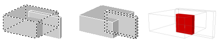
Interference checking creates temporary solid or surface objects and highlights where the models intersect.
If the selection set contains both 3D solids and surfaces, the resulting interference object is a surface. You cannot check interference for mesh objects. However, if you select mesh objects, you can choose to convert them to a solid or surface object and continue the operation.
During the checking operation, you can use the Interference Checking dialog box to cycle through and zoom to interference objects. You can also specify whether to delete the temporary objects that are created during interference checking. You can check interference using the following methods
- Define one selection set. Check the interference of all the 3D solids and surfaces in a single selection set.
- Define two selection sets. Check the interference of the objects in the first set of objects against the objects in the second selection set.
- Individually specify solids that are nested within blocks or xrefs. Individually select 3D solid or surface objects that are nested in blocks and external references (xrefs) and compare them against other objects in the selection set.
