You can create a single layout viewport that fits the entire layout or create multiple layout viewports in the layout. Once you create the viewports, you can change their size, their properties, and also scale and move them as needed.
It is important to create layout viewports on their own layer. When you are ready to plot, you can turn off the layer and plot the layout without plotting the boundaries of the layout viewports. With MVIEW, you have several options for creating one or more layout viewports. You can also use COPY and ARRAY to create multiple layout viewports.
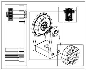
Nonrectangular Layout Viewports – You can create a new viewport with nonrectangular boundaries by converting an object drawn in paper space into a layout viewport.
You can use the MVIEW command to create nonrectangular viewports.
- With the Object option, you can select a closed object, such as a circle or closed polyline created in paper space, to convert into a layout viewport. The object that defines the viewport boundary is associated with the viewport after the viewport is created
- With the Polygonal option, you can create a nonrectangular layout viewport by specifying points. The prompts are the same as the prompts for creating a polyline
When you want to suppress the display of the boundary of a layout viewport, you should turn off the layer of the nonrectangular viewport instead of freezing it. If the layer of a nonrectangular layout viewport is frozen, the viewport is not clipped correctly.
Layout Viewport Boundaries – You can redefine the boundary of a layout viewport by using the VPCLIP command. You can either select an existing object to designate as the new boundary, or specify the points of a new boundary. The new boundary does not clip the old boundary, it redefines it.
A nonrectangular viewport consists of two objects: the viewport itself and the clipping boundary. You can make changes to the viewport, the clipping boundary, or both. In the Properties palette, the default selection for a nonrectangular viewport is Viewport. This is because you are more likely to change the properties of the viewport than of the clipping boundary.
Resize Layout Viewports – If you want to change the shape or size of a layout viewport, you can use grips to edit the vertices just as you edit any object with grips.
Scale Views – To scale each displayed view in the plotted drawing accurately, set the scale of each view relative to paper space. You can change the view scale of the viewport using
- The Properties palette
- The XP option of the ZOOM command
- The Viewports toolbar
You can modify the list of scales that are displayed in all view and plot scale lists with SCALELISTEDIT. When you work in a layout, the scale factor of a view in a layout viewport represents a ratio between the actual size of the model displayed in the viewport and the size of the layout. The ratio is determined by dividing the paper space units by the model space units. For example, for a quarter-scale drawing, the ratio would be a scale factor of one paper space unit to four model space units, or 1:4.
Scaling or stretching the layout viewport border does not change the scale of the view within the viewport.
Lock the Scale – Once you set the viewport scale, you cannot zoom within a viewport without changing the viewport scale. By locking the viewport scale first, you can zoom in to view different levels of detail in your viewport without altering the viewport scale.
Scale locking locks the scale that you set for the selected viewport. Once the scale is locked, you can continue to modify the geometry in the viewport without affecting the viewport scale. If you turn a viewport’s scale locking on, most of the viewing commands, such as VPOINT, DVIEW, 3DORBIT, PLAN, and VIEW, no longer function in that viewport.
Viewport scale locking is also available for nonrectangular viewports. To lock a nonrectangular viewport, you must perform an extra step in the Properties palette to select the viewport object rather than the viewport clipping boundary.
Layout Viewports Visibility – You can control the visibility of objects in layout viewports using several methods. These methods are useful for emphasizing or hiding different elements of a drawing, and for reducing screen regeneration time.
A major benefit to using layout viewports is that you can selectively freeze layers in each layout viewport. You can also specify default visibility settings for new viewports and for new layers. As a result, you can view different objects in each layout viewport.
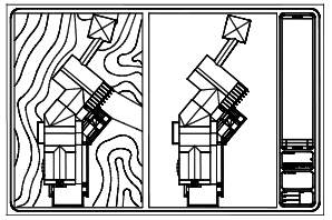
You can freeze or thaw layers in current and future layout viewports without affecting other viewports. Frozen layers are invisible. They are not regenerated or plotted. In the illustration, the layer showing terrain has been frozen in one viewport. Thawing the layer restores visibility. The easiest way to freeze or thaw layers in the current viewport is to use the Layer Properties Manager.
In the Layer Properties Manager, on the right side, use the column labeled VP Freeze to freeze one or more layers in the current layout viewport. To display the VP Freeze column, you must be on a layout tab. Specify the current layout viewport by double-clicking anywhere within its borders.
Freeze Layers Automatically – You can set visibility defaults for specific layers in all new layout viewports. For example, you can restrict the display of dimensions by freezing the DIMENSIONS layer in all new viewports. If you create a viewport that requires dimensions, you can override the default setting by changing the setting in the current viewport. Changing the default for new viewports does not affect existing viewports.
Screening – Screening refers to applying less ink to an object when it is plotted. The object appears dimmer on the screen and on the plotted paper. Screening can be used to help differentiate objects in a drawing without changing the objects’ color properties.
To assign a screening value to an object, you must assign a plot style to the object, and then define the screening value in that plot style.
You can assign a screening value from 0 to 100. The default setting, 100, means no screening is applied, and the object is displayed with normal ink intensity. A screening value of 0 means the object contains no ink and is thus invisible in that viewport.
Viewports On or Off – You can save time by turning some layout viewports off or by limiting the number of active viewports.
Displaying a large number of active layout viewports can affect your system’s performance as the content of each layout viewport regenerates. You can save time by turning some layout viewports off or by limiting the number of active viewports. The following illustration shows the effects of turning off two layout viewports.
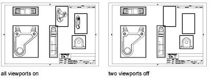
New layout viewports are turned on by default. If you turn off the layout viewports you aren’t using, you can copy layout viewports without waiting for each one to regenerate. If you don’t want to plot a layout viewport, you can turn the layout viewport off.
Scale Linetypes – You can scale linetypes in paper space either based on the drawing units of the space in which the object was created or based on the paper space units.
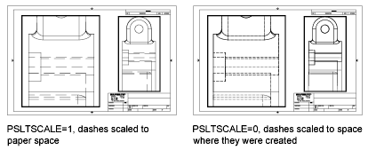
You can set the PSLTSCALE system variable to maintain the same linetype scaling for objects displayed at different zoom factors in a layout and in a layout viewport. For example, with PSLTSCALE set to 1 (default), set the current linetype to dashed, and then draw a line in a paper space layout. In the layout, create a viewport with a zoom factor of 1x, make that layout viewport current, and then draw a line using the same dashed linetype. The dashed lines should appear to be the same. If you change the viewport zoom factor to 2x, the linetype scaling for the dashed line in the layout and the dashed line in the layout viewport will be the same, regardless of the difference in the zoom factor.
With PSLTSCALE turned on, you can still control the dash lengths with LTSCALE and CELTSCALE. In the following illustration, the pattern of the linetypes in the drawing on the left has been scaled to be the same regardless of the scale of the view. In the drawing on the right, the scale of the linetypes matches the scale of each view.
Align Views – You can arrange the elements of your drawing by aligning the view in one layout viewport with the view in another viewport.
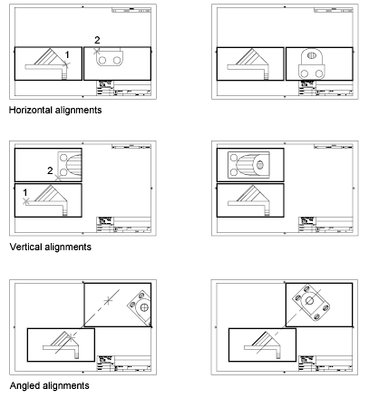
For angled, horizontal, and vertical alignments, you can move each layout viewport relative to distances defined by the model-space geometry displayed.
To adjust the views on a layout with precision, you can create construction geometry, use object snaps on the model-space objects displayed in layout viewports, or use one of the cursor constraint features available on the status bar.
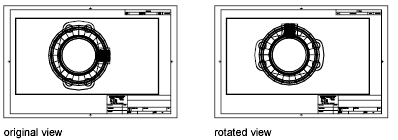
Rotate Views – You can rotate an entire view within a layout viewport with the VPROTATEASSOC system variable. When VPROTATEASSOC is set to 1, the view within a viewport is rotated with the viewport. When VPROTATEASSOC is set to 0, the view remains when the viewport is rotated.
You can also rotate an entire view within a layout viewport by changing the UCS and using the PLAN command. With the UCS command, you can rotate the XY plane at any angle around the Z axis. When you enter the PLAN command, the view rotates to match the orientation of the XY plane.
Another way is touse the Align and then Rotate View options in the MVSETUP command.
The ROTATE command rotates individual objects only and should not be used to try to rotate a view.
Layout Template – When you create a layout, you can choose to apply the information from an existing template.
A layout template is a layout imported from a DWG or DWT file. When you create a layout, you can choose to apply the information from an existing template. The program has sample layout templates to use when you design a new layout environment. The paper space objects and page setup in the existing template are used in the new layout. Thus, the layout objects, including any viewport objects, are displayed in paper space. You can keep any of the existing objects from the template you import, or you can delete the objects. No model space objects are imported.
The layout templates are identified with a .dwt file extension. However, a layout template or layout from any drawing or drawing template can be imported into the current drawing.
Any drawing can be saved as a drawing template (DWT file), including all of the objects and layout settings. You can save a layout to a new DWT file by choosing the Save As option of the LAYOUT command. The template file is saved in the drawing template file folder as defined in the Options dialog box, Support tab. The layout template has a .dwt or .dwg extension like a drawing template or drawing file, but it contains little information not essential to the layout.
When you create a new layout template, any named items, such as blocks, layers, and dimension styles, that are used in the layout are saved with the template. These definition table items are imported as part of the layout settings if you import this template into a new layout. It is recommended that you use the Save As option of the LAYOUT command to create a new layout template. When you use the Save As option, unused definition table items are not saved with the file; they are not added to the new layout into which you import the template.
If you insert a layout from a drawing or template that was not created using the Save As option of the LAYOUT command, definition table items that are used in the drawing but not in the layout are inserted with the layout. To eliminate unnecessary definition table items, use the PURGE command.
