Dimensioning
Dimensioning is the process of adding measurement annotation to a drawing. You can create dimensions for a variety of object types in many orientations. The basic types of dimensioning are
- Linear
- Radial (radius, diameter and jogged)
- Angular
- Ordinate
- Arc Length
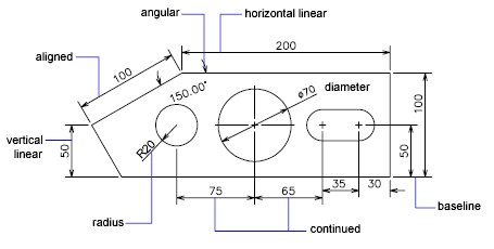
Linear dimensions can be horizontal, vertical, aligned, rotated, baseline, or continued (chained). Some examples are shown in the illustration.
To simplify drawing organization and dimension scaling, it is recommended that you create dimensions on layouts rather than in model space.
Parts of a Dimension
Here is a list of the parts of a dimension along with their descriptions. Dimensions have several distinct elements: dimension text, dimension lines, arrowheads, and extension lines.
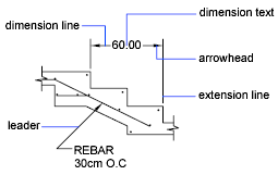
- Dimension text is a text string that usually indicates the measurement value. The text can also include prefixes, suffixes, and tolerances.
- A dimension line indicates the direction and extent of a dimension. For angular dimensions, the dimension line is an arc.
- Arrowheads, also called symbols of termination, are displayed at each end of the dimension line. You can specify different sizes and shapes for arrowheads or tick marks.
- Extension lines, also called projection lines or witness lines, extend from the feature to the dimension line.
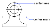
- A center mark is a small cross that marks the center of a circle or arc.
- Centerlines are broken lines that mark the center of a circle or arc.
Associative Dimensions
Dimensions can be associative, nonassociative, or exploded. Associative dimensions adjust to changes in the geometric objects that they measure. Dimension associativity defines the relationship between geometric objects and the dimensions that give their distance and angles. There are three types of associativity between geometric objects and dimensions.
- Associative dimensions. Automatically adjust their locations, orientations, and measurement values when the geometric objects associated with them are modified. Dimensions in a layout may be associated to objects in model space. The DIMASSOC system variable is set to 2.
- Nonassociative dimensions. Selected and modified with the geometry they measure. Nonassociative dimensions do not change when the geometric objects they measure are modified. The dimension variable DIMASSOC is set to 1.
- Exploded dimensions. Contain a collection of separate objects rather than a single dimension object. The DIMASSOC system variable is set to 0.
You can determine whether a dimension is associative or nonassociative by selecting the dimension and doing one of the following:
- Use the Properties palette to display the properties of the dimension.
- Use the LIST command to display the properties of the dimension.
- You can also use the Quick Select dialog box to filter the selection of associative or nonassociative dimensions. A dimension is considered associative even if only one end of the dimension is associated with a geometric object. The DIMREASSOCIATE command displays the associative and nonassociative elements of a dimension.
Dimension Styles
A dimension style is a named collection of dimension settings that controls the appearance of dimensions, such as arrowhead style, text location, and lateral tolerances. You create dimension styles to specify the format of dimensions quickly, and to ensure that dimensions conform to industry or project standards.
When you create a dimension, it uses the settings of the current dimension style If you change a setting in a dimension style, all dimensions in a drawing that use the style update automatically
You can create dimension substyles that, for specified types of dimensions, deviate from the current dimension style If necessary, you can override a dimension style temporarily
Geometric Tolerances
Geometric tolerances show acceptable deviations of form, profile, orientation, location, and runout of a feature. You add geometric tolerances in feature control frames. These frames contain all the tolerance information for a single dimension. Geometric tolerances can be created with or without leader lines, depending on whether you create them with TOLERANCE or LEADER.
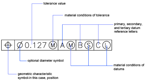
A feature control frame consists of two or more components. The first feature control frame contains a symbol that represents the geometric characteristic to which a tolerance is being applied, for example, location, profile, form, orientation, or runout. Form tolerances control straightness, flatness, circularity and cylindricity; profiles control line and surface. In the illustration, the characteristic is position.
You can use most editing commands to change feature control frames, and you can snap to them using the object snap modes. You can also edit them with grips. Unlike dimensions and leaders, geometric tolerances cannot be associated with geometric objects.
Material Conditions
Material conditions apply to features that can vary in size. The second compartment contains the tolerance value. Depending on the control type, the tolerance value is preceded by a diameter symbol and followed by a material condition symbol. Material conditions apply to features that can vary in size
- At maximum material condition (symbol M, also known as MMC), a feature contains the maximum amount of material stated in the limits.
- At MMC, a hole has minimum diameter, whereas a shaft has maximum diameter.
- At least material condition (symbol L, also known as LMC), a feature contains the minimum amount of material stated in the limits.
- At LMC, a hole has maximum diameter, whereas a shaft has minimum diameter.
- Regardless of feature size (symbol S, also known as RFS) means a feature can be any size within the stated limits.
Datum Reference Frames
The tolerance values in the feature control frame are followed by up to three optional datum reference letters and their modifying symbols. A datum is a theoretically exact point, axis, or plane from which you make measurements and verify dimensions. Usually, two or three mutually perpendicular planes perform this task best. These are jointly called the datum reference frame.
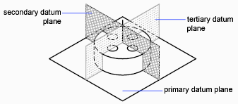
The following illustration shows a datum reference frame verifying the dimensions of the part.
Projected Tolerance Zones
Projected tolerances are used to make the tolerance more specific. Projected tolerances are specified in addition to positional tolerances to make the tolerance more specific. For example, projected tolerances control the perpendicularity tolerance zone of an embedded part.
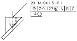
The symbol for projected tolerance ( ) is preceded by a height value, which specifies the minimum projected tolerance zone. The projected tolerance zone height and symbol appear in a frame below the feature control frame, as shown in the following illustration.
Composite Tolerances
A composite tolerance specifies two tolerances for the same geometric characteristic of a feature or for features that have different datum requirements. One tolerance relates to a pattern of features and the other tolerance to each feature within the pattern. The individual feature tolerance is more restrictive than the pattern tolerance.
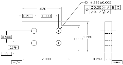
In the following illustration, the point where datums A and B intersect is called the datum axis, the point from which the position of the pattern is calculated. A composite tolerance could specify both the diameter of the pattern of holes and the diameter of each individual hole, as in the following illustration.
When you add composite tolerances to a drawing, you specify the first line of a feature control frame and then choose the same geometric characteristic symbol for the second line of the feature control frame. The geometric symbol compartment is extended over both lines. You can then create a second line of tolerance symbols.
