Draw Arcs
To create an arc, you can specify various combinations of center, endpoint, start point, radius, angle, chord length, and direction values. You can create arcs in several ways. With the exception of the first method, arcs are drawn counterclockwise from the start point to the endpoint.
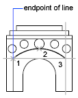
Draw Arcs by Specifying Three Points – You can create an arc by specifying three points. In the following example, the start point of the arc snaps to the endpoint of a line. The second point of the arc snaps to the middle circle in the illustration.
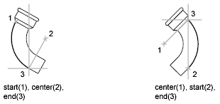
Draw Arcs by Specifying Start, Center, End – You can create an arc using a start point, center, and a third point that determines the endpoint. The distance between the start point and the center determines the radius. The endpoint is determined by a line from the center that passes through the third point. The resulting arc is always created counterclockwise from the start point. Using different options, you can specify either the start point first or the center point first.
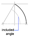
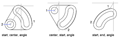
Draw Arcs by Specifying Start, Center, Angle – You can create an arc using a start point, center, and an included angle. The distance between the start point and the center determines the radius. The other end of the arc is determined by specifying an included angle that uses the center of the arc as the vertex. The resulting arc is always created counterclockwise from the start point. Using different options, you can specify either the start point first or the center point first.
The included angle determines the endpoint of the arc. Use the Start, End, Angle method when you know both endpoints but cannot snap to a center point.
Draw Arcs by Specifying Start, Center, Length – You can create an arc using a start point, center, and the length of a chord. The distance between the start point and the center determines the radius. The other end of the arc is determined by specifying the length of a chord between the start point and the endpoint of the arc. The resulting arc is always created counterclockwise from the start point. Using different options, you can specify either the start point first or the center point first.
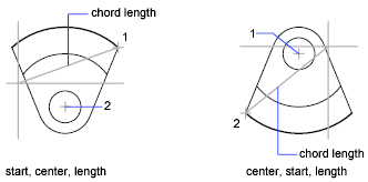
The length of the chord of the arc determines the included angle.
Draw Arcs by Specifying Start, End, Angle – You can create an arc using a start point, endpoint, and an included angle. The included angle between the endpoints of the arc determines the center and the radius of the arc.
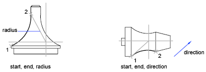
Draw Arcs by Specifying Start, End, Direction – You can create an arc using a start point, endpoint, and a tangent direction at the start point. The tangent direction can be specified either by locating a point on the desired tangent line, or by entering an angle. You can determine which endpoint controls the tangent by changing the order in which you specify the two endpoints.
Draw Arcs by Specifying Start, End, Radius – You can create an arc using a start point, endpoint, and a radius. The direction of the bulge of the arc is determined by the order in which you specify its endpoints. You can specify the radius either by entering it or by specifying a point at the desired radius distance.
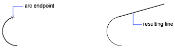
Draw Contiguous Tangent Arcs and Lines – Immediately after you create an arc, you can start a line that is tangent to the arc at an endpoint by starting the LINE command and pressing ENTER at the Specify First Point prompt. You need to specify only the line length.
Immediately after you create a line or an arc, you can start an arc that is tangent at an endpoint by starting the ARC command and pressing ENTER at the Specify Start Point prompt. You need to specify only the endpoint of the new arc.
Draw Circles
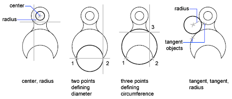
To create circles, you can specify various combinations of center, radius, diameter, points on the circumference, and points on other objects. You can create circles in several ways. The default method is to specify the center and the radius. Three other ways to draw a circle are shown in the illustration.
Draw Polyline Arcs
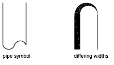
A polyline is a connected sequence of line segments created as a single object. You can create straight line segments, arc segments, or a combination of the two.
Multisegmented lines provide editing capabilities unavailable for single lines. For example, you can adjust their width and curvature. After you’ve created a polyline, you can edit it with PEDIT or use EXPLODE to convert it to individual line and arc segments. You can
- Convert a spline-fit polyline into a true spline with SPLINE
- Use closed polylines to create a polygon
- Create a polyline from the boundaries of overlapping objects
Draw Donuts
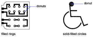
Donuts are filled rings or solid-filled circles that actually are closed polylines with width. To create a donut, you specify its inside and outside diameters and its center. You can continue creating multiple copies with the same diameter by specifying different center points. To create solid-filled circles, specify an inside diameter of 0.
Draw Ellipses
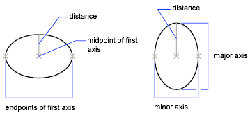
The shape of an ellipse is determined by two axes that define its length and width. The longer axis is called the major axis, and the shorter one is the minor axis.
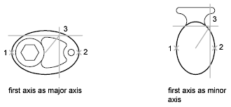
The illustrations below show two different ellipses created by specifying axis and distance. The third point specifies only a distance and does not necessarily designate the axis endpoint. If you are drawing on isometric planes to simulate 3D, you can use ellipses to represent isometric circles viewed from an oblique angle. First you need to turn on Isometric Snap in the Drafting Settings dialog box.
Draw Splines
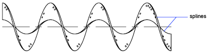
A spline is a smooth curve that passes through or near a given set of points. You can control how closely the curve fits the points. The SPLINE command creates a particular type of spline known as a nonuniform rational B-spline (NURBS) curve. A NURBS curve produces a smooth curve between control points.
You create splines by specifying points. You can close the spline so that the start and endpoints are coincident and tangent. Tolerance describes how closely the spline fits the set of fit points you specify. The lower the tolerance, the more closely the spline fits the points. At zero tolerance, the spline passes through the points. You can change the spline-fitting tolerance while drawing the spline to see the effect. You can use two methods for creating splines
- Create spline curves with the Spline option of PEDIT to smooth existing polylines created with PLINE. Such spline-fit polylines are created with uniform knot vectors and are more likely to be included in drawings created with earlier versions of the product.
- Create splines, which are NURBS curves, with SPLINE. Drawings containing splines use less memory and disk space than those containing spline-fit polylines of similar shape.
Draw Helixes
A helix is an open 2D or 3D spiral. You can use a helix as a path with the SWEEP command. For example, you might sweep a circle along a helix path to create a solid model of a spring. When you create a helix, you can specify the following.
- Base radius
- Top radius
- Height
- Number of turns
- Turn height
- Twist direction
If you specify the same value for both the base radius and the top radius, then a cylindrical helix is created. By default, the top radius is set to the same value as the base radius. You cannot specify 0 for both the base radius and top radius. If you specify different values for the top radius and the base radius, then a conical helix is created. If you specify a height value of 0, then a flat, 2D spiral is created.
