Construction lines and reference points are temporary objects you create to help you draw accurately.
Reference Points
Point objects are useful as nodes or reference geometry for object snaps and relative offsets. You can set the style of the points and their size relative to the screen or in absolute units. Changing the style of points
- Makes them more visible and easier to differentiate from grid dots
- Affects the display of all point objects in the drawing
- Requires using REGEN to make the change visible
Construction Lines (and Rays)
Lines that extend to infinity in one or both directions, known as rays and construction lines, respectively, can be used as references for creating other objects. For example, you can use construction lines to find the center of a triangle, prepare multiple views of the same item, or create temporary intersections to use for object snaps.
Infinite lines do not change the total area of the drawing. Therefore, their infinite dimensions have no effect on zooming or viewpoints, and they are ignored by commands that display the drawing extents. You can move, rotate, and copy infinite lines just as you can move, rotate, and copy other objects. You may want to create infinite lines on a construction line layer that can be frozen or turned off before plotting.
Construction Lines
A construction line () can be placed anywhere in three-dimensional space. You can specify its orientation in several ways. The default method for creating the line is the two-point method: you specify two points to define the orientation. The first point, the root, is the conceptual midpoint of the construction line, that is, the point snapped to by the Midpoint object snap. You can also create construction lines in several other ways.
- Horizontal and Vertical. Create construction lines that pass through a point you specify and are parallel to the X or Y axis of the current UCS.
- Creates a construction line in one of two ways. Either you select a reference line and then specify the angle of the construction line from that line, or you create a construction line at a specific angle to the horizontal axis by specifying an angle and then a point through which the construction line should pass.
- Creates a construction line that bisects an angle you specify. You specify the vertex and the lines that create the angle.
- Creates a construction line parallel to a baseline you specify. You specify the offset distance, select the baseline, and then indicate on which side of the baseline to locate the construction line.
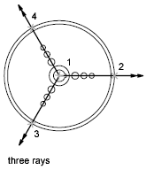
Rays
A ray is a line in three-dimensional space that starts at a point you specify and extends to infinity. Unlike construction lines, which extend in two directions, rays extend in only one direction. Using rays instead of construction lines can help reduce visual clutter. Like construction lines, rays are ignored by commands that display the drawing extents.