You can use several methods to create blocks:
- Combine objects to create a block definition in your current drawing.
- Use the Block Editor contextual tab (when the ribbon is active) or Block Editor (when the ribbon is not active) to add dynamic behavior to a block definition in your current drawing.
- Create a drawing file and later insert it as a block in other drawings.
- Create a drawing file with several related block definitions to serve as a block library.
You can use PURGE to remove unused block definitions from a drawing. Every drawing file has an invisible data area called the block definition table. The block definition table stores all block definitions, which consist of all information associated with the block. It is these block definitions that are referenced when you insert blocks in your drawing.
The following illustrations are conceptual representations of three drawing files. Each rectangle represents a separate drawing file and is divided into two parts: the smaller part represents the block definition table, and the larger part represents the objects in a drawing.
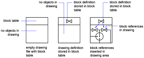
When you insert a block, you are inserting a block reference. The information is not simply copied from the block definition to the drawing area. Instead, a link is established between the block reference and the block definition. Therefore, if the block definition is changed, all references are updated automatically.
To reduce the size of a drawing, you can purge unused block definitions.
Create Blocks Within a Drawing
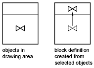
After you define a block in a drawing, you can insert a block reference in the drawing as many times as necessary. Use this method to create blocks quickly. Each block definition includes a block name, one or more objects, the coordinate values of the base point to be used for inserting the block, and any associated attribute data.
The base point is used as a reference for positioning the block when you insert it. Suppose you specify that the base point is at the lower-left corner of an object in the block. Later, when you insert the block, you are prompted for an insertion point. The block base point is aligned at the insertion point you specified.
The block definition in the illustration comprises a name, PLUG_VALVE, four lines, and a base point at the intersection of the two diagonal lines. For an explanation of the schematic representation shown, see Overview of Blocks.
Create Drawing Files for Use as Blocks
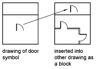
You can create individual drawing files for use as blocks. You can create drawing files for the purpose of inserting them into other drawings as blocks. Individual drawing files are easy to create and manage as the source of block definitions. Collections of symbols can be stored as individual drawing files and grouped in folders.
Color and Linetype Properties
The objects in an inserted block can retain their original properties, can inherit properties from the layer on which they are inserted, or can inherit the properties set as current in the drawing. Generally when you insert a block, the color, linetype, and lineweight of objects in the block retain their original settings regardless of the current settings in the drawing. However, you can create blocks with objects that inherit the current color, linetype, and lineweight settings. These objects have floating properties.
You have three choices for how the color, linetype, and lineweight properties of objects are treated when a block reference is inserted.
- Objects in the block do not inherit color, linetype, and lineweight properties from the current settings. The properties of objects in the block do not change regardless of the current settings. For this choice, it is recommended that you set the color, linetype, and lineweight properties individually for each object in the block definition: do not use BYBLOCK or BYLAYER color, linetype, and lineweight settings when creating these objects.
- Objects in the block inherit color, linetype, and lineweight properties from the color, linetype, and lineweight assigned to the current layer only. For this choice, before you create objects to be included in the block definition, set the current layer to 0, and set the current color, linetype, and lineweight to BYLAYER.
- Objects inherit color, linetype, and lineweight properties from the current color, linetype, and lineweight that you have set explicitly, that is, that you have set to override the color, linetype, or lineweight assigned to the current layer. If you have not explicitly set them, then these properties are inherited from the color, linetype, and lineweight assigned to the current layer. For this choice, before you create objects to be included in the block definition, set the current color or linetype to BYBLOCK.
Nest Blocks
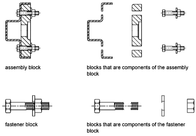
Block references that contain other blocks are known as nested blocks. Using blocks within blocks can simplify the organization of a complex block definition. With nested blocks, you can build a single block out of several components. For example, you can insert as a block a drawing of a mechanical assembly that contains a housing, a bracket, and fasteners in which each fastener is a block composed of a bolt, washer, and nut. The only restriction on nested blocks is that you cannot insert blocks that reference themselves.
You can apply geometric constraints and constraint parameters to nested objects in blocks. AutoCAD detects the nested entity or valid constraint point for the nested entity regardless of the nesting level of the object. Constraints can only be applied between nested objects in the block and objects in the drawing file, not between pairs of nested objects in the block reference.
When a block definition is redefined, AutoCAD will re-evaluate the constraints between geometry in the drawing and the nested geometry in the block references. The drawing will then be updated appropriately. If a constraint cannot be resolved as a result of the change to the block definition, then the constraint is removed and an unresolved constraints message is displayed at the command line.
Block Libraries
A block library is a collection of block definitions stored in a single drawing file. You can use block libraries supplied by Autodesk or other vendors or create your own. You can organize a set of related block definitions by creating the blocks in the same drawing file. Drawing files used this way are called block, or symbol, libraries. These block definitions can be inserted individually into any drawing that you are working on. Block library drawings are not different from other drawing files except in how they are used. When you use BLOCK to define each block definition in the block library drawing, you can include a short description of the block that can be viewed in DesignCenter.
