Select Objects
You have a wide range of options when you need to select objects for editing operations as
- Use the Pickbox Cursor – When the square pickbox cursor is in position to select an object, the object is highlighted. Click to select the object. You can control the size of the pickbox in the Options dialog box, Selection tab.
- Select Objects Close Together – It is difficult to select objects that are close together or lie directly on top of one another. The example shows two lines and a circle that lie within the pickbox.
- At the Select Objects prompt, you can select many objects at the same time. With a window selection, usually the entire object must be contained in the rectangular selection area. However, if an object with a noncontinuous (dashed) linetype is only partially visible in the viewport and all the visible vectors of the linetype can be enclosed within the selection window, the entire object is selected. You can see all selection options by entering ? at the Select Objects prompt. For a description of each of the selection options, see SELECT.
- Prevent Objects from Being Selected – You can prevent objects on specified layers from being selected and modified by locking those layers. Typically, you lock layers to prevent accidental editing of particular objects. Other operations are still possible when a layer is locked. For example, you can make a locked layer current, and you can add objects to it. You can also use inquiry commands (such as LIST), use object snaps to specify points on objects on locked layers, and change the draw order of objects on locked layers.
- Filter Selection Sets – You can use object properties or object types to include objects in a selection set, or to exclude them. Using either Quick Select ( QSELECT) from the Properties palette or the Object Selection Filters dialog box ( FILTER), you can filter selection sets by property (such as color) and by object type. For example, you can select all of the red circles in a drawing without selecting any other object, or you can select all objects except the red circles.
- Customize Object Selection – You can control several aspects of selecting objects, such as whether you enter a command first or select objects first, the size of the pickbox cursor, and how selected objects are displayed.
- Group Objects – A group is a saved set of objects that you can select and edit together or separately as needed. Groups provide an easy way to combine drawing elements that you need to manipulate as a unit.
Erase Objects
There are many ways to delete objects from your drawing and clean up the display.
- Remove Unused Definitions, Styles, and Objects – You can remove unused named and unnamed objects with PURGE. Some of the unnamed objects you can purge include block definitions, dimension styles, layers, linetypes, and text styles. With PURGE you can also remove zero-length geometry and empty text objects.
- Clean Up the Display – You can remove the plus-shaped markers called blips and stray pixels that may be left over from some editing operations from the display area. To remove blips, use REDRAW. To remove stray pixels, use REGEN.
Windows Cut, Copy, and Paste
When you want to use objects from a drawing file in another application, you can cut or copy these objects to the Clipboard and then paste them from the Clipboard into the other application.
You can use the Clipboard to copy part or all of a drawing into a document created by another application. The objects are copied in vector format, which retains the high resolution in other applications. These objects are stored in WMF (Windows metafile) format in the Clipboard. The information stored in the Clipboard can then be embedded in the other document. Updating the original drawing does not update the copy embedded in the other application.
Applications use different internal formats to store Clipboard information. When you copy objects to the Clipboard, information is stored in all available formats. When you paste the Clipboard contents into a drawing, the format that retains the most information is used. However, you can override this setting and convert pasted information to AutoCAD format.
Because it is the easiest format to edit, the AutoCAD format is the preferred format for copying objects to and from AutoCAD. It retains all relevant object information, including block references and 3D aspects.
Fillets
A fillet connects two objects with an arc that is tangent to the objects and has a specified radius.
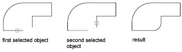
An inside corner is called a fillet and an outside corner is called a round; you can create both using the FILLET command.
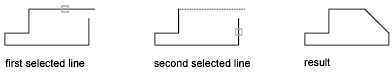
Chamfers
A chamfer connects two objects to meet in a flattened or beveled corner. A chamfer connects two objects with an angled line. It is usually used to represent a beveled edge on a corner.
Break Objects
Use BREAK to create a gap in an object, resulting in two objects with a gap between them. BREAK is often used to create space for block or text.
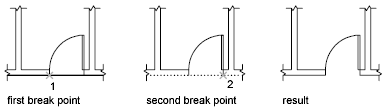
To break an object without creating a gap, specify both break points at the same location. The fastest way to do this is to enter @0,0 at the prompt for the second point.
Join Objects
Use JOIN to combine similar objects into a single object. You can also create complete circles and ellipses from arcs and elliptical arcs. You can join
- Arcs
- Elliptical arcs
- Lines
- Polylines
- Splines
The object to which you want to join similar objects is called a source object. Objects to be joined must be located in the same plane. Additional restrictions for each type of objects are described in the JOIN command.
Trim Objects
You can trim objects so that they end precisely at boundary edges defined by other objects. For example, you can clean up the intersection of two walls smoothly by trimming.
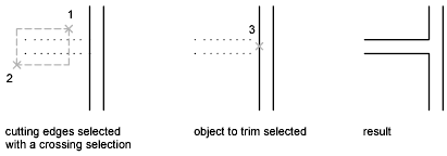
An object can be one of the cutting edges and one of the objects being trimmed. For example, in the illustrated light fixture, the circle is a cutting edge for the construction lines and is also being trimmed.
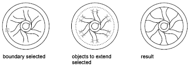
Extend Objects
Extending operates the same way as trimming. You can extend objects so they end precisely at boundary edges defined by other objects. In this example, you extend the lines precisely to a circle, which is the boundary edge.
You can trim objects without leaving the EXTEND command. Hold down Shift and select the objects to be trimmed.
Create a Block
To create a block, follow these steps:
- Draw the objects that you want in the block.autocad_tips_create-a-block-in-autocad-1
- Choose Home tab> Block panel> Create to start the BLOCK command. The Block Definition dialog box opens.
- Type a name in the Name text box. The name can have spaces.
- You need to specify a base point. That’s the point at which you’ll insert the block. In the Base Point section, click Pick Point. Be sure to use an object snap for accuracy! You’ll immediately be returned to the dialog box.
- In the Objects section, click the Select Objects button. Select the objects and press Enter to return to the dialog box. Tip: You can select the objects before using the command and they’ll show up in the dialog box.
- Just below, choose Retain, Convert to Block, or Delete. These options control what happens after you create the block.
- In the Behavior section, you can make a block Annotative (more info here), force it to scale uniformly and choose whether to allow exploding.
- In the Settings area, choose the block unit. You can choose Unitless but if you choose a unit, AutoCAD will try to scale the block appropriately when you insert it into another drawing. You can also add a hyperlink if you want.
- Finally, you can add a description in the Description box. A description is helpful in the DesignCenter, when you want to insert the block from another drawing.
- Click OK to complete the box. If you chose Delete, the objects disappear. You can use the OOPS command to bring them back.
