Computer-aided design (CAD) is the use of computer systems to aid in the creation, modification, analysis, or optimization of a design. CAD software is used to increase the productivity of the designer, improve the quality of design, improve communications through documentation, and to create a database for manufacturing. CAD output is often in the form of electronic files for print, machining, or other manufacturing operations. The term CADD (for Computer Aided Design and Drafting) is also used.
The evolution of the informatics has increasing influence in every field of the our life, so the engineering is not mean exception. The work of engineers is changing, we can solve more complex problems, but the different software tools ensure effective and productive work.
CAD may be used to design curves and figures in two-dimensional (2D) space; or curves, surfaces, and solids in three-dimensional (3D) space.
CAD is an important industrial art extensively used in many applications, including automotive, shipbuilding, and aerospace industries, industrial and architectural design, prosthetics, and many more. CAD is also widely used to produce computer animation for special effects in movies, advertising and technical manuals, often called DCC digital content creation. The modern ubiquity and power of computers means that even perfume bottles and shampoo dispensers are designed using techniques unheard of by engineers of the 1960s. Because of its enormous economic importance, CAD has been a major driving force for research in computational geometry, computer graphics (both hardware and software), and discrete differential geometry.
A CAD system can be a simple 2D drawing system or a parametric associative hybrid modelling system. The up-to-date method is this last concept, where
- the parametric means the dimension driven modelling,
- the associative means the live connection between the geometric elements,
- the hybrid means the parallel and synergic surface and solid modelling.
CAD Classification
The CAD systems can be classified by several viewpoint
- The first is the application field. The CAD systems are developed in every industrial areas, so we can find systems in the field of mechanical engineering, electric engineering, architectural design, civil engineering, cloth and shoe design, medical application.
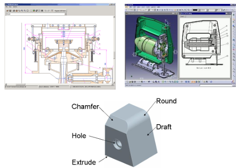
- The type of the modelling can be 2D, when the representation of the part is similar to the engineering drawing. The other method is the 3D modelling, when the model of the part is build in the virtual space.
- The applied modelling method can be wireframe modelling, when only the edges of the part are defined. In case of surface modelling the CAD model is hollow, only the boundary „skin” is defined. The solid modelling ensures realistic representation, the model consists of simple elementary elements.
- In case of parametric model, the size of the model is driven by the geometric parameters. The size of a non-parametric model is defined by user’s modelling activity and the dimensioning value is driven by the modelled object.
CAD Application
The typical application fields are
- Mechanical engineering
- Electronic design
- Architectural design
- Civil engineering
- Textile industry
- Medical
Product Creation and Development
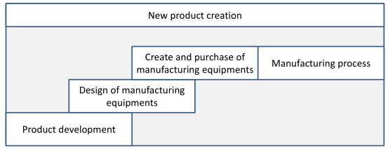
The new product creation process consists of four main step.
- The first is the product development, when the full design documentation is produced based on the market, customer and financial requirements.
- The production needs manufacturing equipments, like tools, machine tools, moulds etc. And if there are no exist, we have to design them. Then the manufacturing equipments have to purchase or create, which sometimes need lot of time and it has a high cost.
- The last step is the production, which means part production and assembly.
- As the figure shows, some sub-processes can be performed with overlapping in order to reduce the lead time.
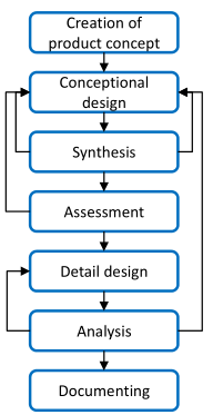
The steps of the product development are the next in general case
- Creation of product concept. The function, engineering, quality, market and other requirements are collected in order to define the aim of the development.
- Conceptional design. The possible solution of each requirements are summarized.
- Unite the separated elements.
- Design assessment. The result is investigated in order to check, than it is suitable for the initial requirements.
- Detail design. The details of the product are designed.
- Analysis of the design. The product design is complete for analysis and every of important properties can be tested.
- The result of the design process is the full design documentation.
CAx Technologies
The product development and production process is supported by computer software. The name of this technology is CAx – computer aided something. These software tools support the specific engineering activities. The help of the computer means different things. In case of manufacturing the CNC programs are generated by a CAM system, the CAE means the collection of every engineering analysis and calculation. The task of the CAPP is to generate a process plan for manufacturing. The CAQA is the programming of coordinate measurement machines in general.
The most often used abbreviations are the next:
- CAD – computer aided design
- CAM – computer aided manufacturing
- CAE – computer aided engineering
- CAPP – computer aided process planning
- CAQA – computer aided quality assurance
- CAPPS – computer aided production planning and scheduling
- CAST – computer aided storage and transport
