
Certify and Increase Opportunity.
Be
Govt. Certified Linux Administrator
TCP/IP provides end-to-end connectivity specifying how data should be formatted, addressed, transmitted, routed and received at the destination. The TCP/IP model and related protocols are maintained by the (IETF) or Internet Engineering Task Force. The Internet protocol suite and the layered protocol stack design were in use before the OSI model was established. It has four abstraction layers, each with its own protocols. It has four abstraction layers, each with its own protocols. From highest to lowest, the layers are
- Application layer (process-to-process)- It contains all protocols (like HTTP) for specific data communications services on a process-to-process level (for example how a web browser communicates with a web server). This is the scope within which applications create user data and communicate this data to other processes or applications on another or the same host. The communications partners are often called peers. This is where the “higher level” protocols such as SMTP, FTP, SSH, HTTP, etc. operate.
- Transport layer (host-to-host)- It handles host-to-host communication. The transport layer constitutes the networking regime between two network hosts, either on the local network or on remote networks separated by routers. The transport layer provides a uniform networking interface that hides the actual topology (layout) of the underlying network connections. This is where flow-control, error-correction, and connection protocols exist, such as TCP. This layer deals with opening and maintaining connections between Internet hosts.
- Internet layer (internetworking)- It connects local networks, thus establishing internetworking. The internet layer has the task of exchanging datagrams across network boundaries. It is therefore also referred to as the layer that establishes internetworking, indeed, it defines and establishes the Internet. This layer defines the addressing and routing structures used for the TCP/IP protocol suite. The primary protocol in this scope is the Internet Protocol, which defines IP addresses. Its function in routing is to transport datagrams to the next IP router that has the connectivity to a network closer to the final data destination.
- Link layer- The link layer (commonly Ethernet) contains communication technologies for a local network. This layer defines the networking methods within the scope of the local network link on which hosts communicate without intervening routers. This layer describes the protocols used to describe the local network topology and the interfaces needed to affect transmission of Internet layer datagrams to next-neighbor hosts.
Internet Protocol
The OSI physical layer and data link layer do not define how to deliver data between devices interconnected with multiple devices. The OSI network layer provides the end-to-end delivery of data between endpoints with any type of physical network in between. The network layer specifies data routing. IP is the primary protocol in the Internet Layer of the Internet Protocol Suite and has the task of delivering datagrams from the source host to the destination host solely based on the addresses. For this purpose, IP defines datagram structures that encapsulate the data to be delivered. It also defines addressing methods that are used to label the datagram source and destination. OSI network layer has following functions which include
- Logical addressing – Sending the data packet from one network to another network requires logical addressing. It helps to distinguish source and destination systems. Network layer adds header to data coming from upper layers and include logical address of sender and receiver. Every host in the network must have a unique address that determines where it is. This address is normally assigned from a hierarchical system.
- Routing – As networks are divided into subnetworks and connect to other networks for wide-area communications, networks use gateways or routers to route packets to their final destination. It is also called as the process of forwarding packets (Layer 3 PDUs)
- Routing protocol – A protocol used by routers to learn dynamically about addresses in a network, for decision making during routing or forwarding process.
IP Packets – IP packets are composed of a header and payload as shown

IP Header
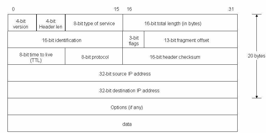
The IPv4 packet header consists of
- 4 bits that contain the version, that specifies if it’s an IPv4 or IPv6 packet,
- 4 bits that contain the Internet Header Length, which is the length of the header in multiples of 4 bytes (e.g., 5 means 20 bytes) and thus points to the beginning of the data. The minimum value for a correct header is 5.
- 8 bits that contain the Type of Service, also referred to as Quality of Service (QoS), which describes what priority the packet should have. The major choice is a three way tradeoff between low-delay, high-reliability, and high-throughput. The distribution is as – Bits 0-2: Precedence, Bit 3: 0 = Normal Delay, 1 = Low Delay, Bit 4: 0 = Normal Throughput, 1 = High Throughput, Bit 5: 0 = Normal Reliability, 1 = High Reliability and Bit 6-7: Reserved for Future Use.
- 16 bits that contain the length of the packet in bytes, including internet header and data. This field allows the length of a datagram to be up to 65,535 bytes.
- 16 bits that contain identification tag to help reconstruct the packet from several fragments.
- 3 bits. The first contains a zero, followed by a flag that says whether the packet is allowed to be fragmented or not (DF or Don’t fragment), and a flag to state whether more fragments of a packet follow (MF or More Fragments). The values are as – Bit 0: reserved, must be zero, Bit 1: (DF) 0 = May Fragment, 1 = Don’t Fragment and Bit 2: (MF) 0 = Last Fragment, 1 = More Fragments.
- 13 bits that contain the fragment offset, a field to identify position of fragment within original packet. The fragment offset is measured in units of 8 bytes. The first fragment has offset zero.
- 8 bits that contain the Time to live (TTL), which is the number of hops (router, computer or device along a network) the packet is allowed to pass before it dies (for example, a packet with a TTL of 16 will be allowed to go across 16 routers to get to its destination before it is discarded),
- 8 bits that contain the protocol (TCP, UDP, ICMP, etc.)
- 16 bits that contain the Header Checksum, a number used in error detection. The checksum field is the 16 bit one’s complement of the one’s complement sum of all 16 bit words in the header. For purposes of computing the checksum, the value of the checksum field is zero.
- 32 bits that contain the source IP address,
- 32 bits that contain the destination address.
After those 160 bits, optional flags can be added of varied length, which can change as per protocol used, then data that packet carries is added. An IP packet has no trailer. However, an IP packet is often carried as the payload inside an Ethernet frame, which has its own header and trailer.
IP Routing – Data packet is routed from source to destination by passing through one or more routers and networks. The IP Routing protocols enable routers to build up a forwarding table to relate an final destination address with next hop addresses. Various protocols used in routing are BGP (Border Gateway Protocol), IS-IS (Intermediate System – Intermediate System), OSPF (Open Shortest Path First) and RIP (Routing Information Protocol).
IP routing is done on a hop-by-hop basis. IP does not know the complete route to any destination (except directly connected). IP routing provides the IP address of the next-hop router to which the data is sent and the next-hop router is assumed to be closer to destination. IP routing performs the following actions
- Search the routing table for an entry that matches the complete destination IP address (matching network ID and host ID). If found, send the packet to the indicated next-hop router or to the directly connected interface.
- Search the routing table for an entry that matches just the destination network ID. If found, send the packet to the indicated next-hop router or to the directly connected interface. All the hosts on the destination network can be handled with this single routing table entry.
- Search the routing table for an entry labeled “default.” If found, send the packet to the indicated next-hop router.
If none of the steps works, the datagram is undeliverable. If the undeliverable datagram was generated on this host, a “host unreachable” or “network unreachable” error is normally returned to the application that generated the datagram. Each entry in routing table has
- Specification of which network interface the datagram should be passed to for transmission.
- Destination IP address. It is either a host address or network address, as specified by the flag field. A host address with a nonzero host ID identifies one particular host, while a network address has a host ID of 0 and identifies all the hosts on that network.
- IP address of a next-hop router or directly connected network. The next-hop router is not the final destination, but it forwards data to the final destination.
- One flag specifies whether the destination IP address is the address of a network or the address of a host. Another flag says whether the next-hop router field is really a next-hop router or a directly connected interface.
IP routing protocols load routing tables with valid, loop-free routes and involves functions as
- Placing the best route, if more than one route to a subnet is available.
- Removing invalid routes from the routing table.
- Dynamically learn and load routing table for a route to all subnets in the
- Replace lost routes, quickly with best available route, also called convergence time.
- Preventing routing loops.
Every routing protocols publicizes it’s routes as
- Add a route for each subnet directly connected to it.
- Update neighbor router about all directly connected and learned routes.
- Add new routes from neighbors
IP Addressing – An IP address is a 32 bit binary number, looks like the following
00000100 10000000 00000011 00000001
It is divided into four 8-bit chunks, called octet, and represented into decimal number for humans to understand like 4.128.3.1 An IP address consists of two parts
- The leftmost bits specify the network address component, called network ID.
- The rightmost bits specify the host address components, called host ID.
Hosts on a network can communicate with devices in the same network by MAC address but for different networks, a router to move data is needed. Each LAN has a unique network ID and all hosts on that network have same network ID but different host ID. A network ID enables a router to put a packet onto the correct network segment. To decide which network is correct, the router looks up a routing table, which is a table contains entries for network addresses (network ID + all host bits set to 0). Each network interface uses a unique IP address.
A, B, and C Classes of Networks – IP addresses are broken into classes to accommodate different sizes of networks as
- Class A (1-126)- It supports extremely large networks and uses only first octet for the network address and rest three octets for host addresses. The first bit of a Class A address is always 0 but, the lowest number represented is 00000000 (decimal 0), and highest number is 01111111 (decimal 127) both are reserved and cannot be used as a network address. Any address start with 127 is reserved for loopback.
- Class B (128-191)- It supports middle-sized and large-sized networks with first two octets for network address and rest two octets for host addresses. The first two bits of a Class B address is binary number 10; thus, the lowest number represented is 10000000 (decimal 128) and highest number is 1011111 (decimal 191).
- Class C (192-223)- It supports small-sized networks with first three octets for network address and remaining one octet for host addresses. The first three bits of a Class C address is binary number 110 thus, lowest number represented is 11000000 (decimal 192), and the highest number is 11011111 (decimal 223).
- Class D- 224-239 is reserved for multicasting, for a single station to simultaneously transmit a datagrams to multiple recipients. It’s first four bits is binary number 1110.
- Class E- 240-255 is experimental addresses, reserved by the IETF for its research.
The block at the beginning and end of each class is called network address and broadcast address, respectively. These two special IP addresses are reserved and detailed as
- Network address- It has all host bits set to 0 to identify the network itself and cannot be assigned like 46.0.0.0 is the network address of the network containing the host 46.4.64.21.
- Broadcast address- It has all host bits set to 1 and used to send data to all the devices on a network like 46.255.255.255 is the broadcast address of network with host 46.4.64.21. Routers will forward broadcast packets on all interfaces but usually routers disable broadcast-forwarding.
The list of the Class A, B, C, D, E IP address is summarized as
| Class | Leading bits | Start | End | Network Bits | Host Bits |
| A | 0.0.0.0 | 127.255.255.255 | 8 | 24 | |
| B | 10 | 128.0.0.0 | 191.255.255.255 | 16 | 16 |
| C | 110 | 192.0.0.0 | 223.255.255.255 | 24 | 8 |
| D | 1110 | 224.0.0.0 | 239.255.255.255 |
The Internet Corporation for Assigned Network Numbers (ICANN, www.icann.org) is in charge for universal IP address assignment and ICANN, assigns regional authority to other cooperating organizations.
IP Subnetting – Many hosts in the same network segment, adds heavy data transfer thus, the packets become slow because of collision and retransmission, which can be avoided by using subnetting. Subnetting divides a single network address into many segments with each segment having its own unique address by placing routers between network segments and all network segments are connected to the Internet by a single gateway router thus, hiding the actual details of internal network but, is shown as the only IP network address. Other benefits of subnetting are
- Smaller collision domains as collisions in one subnet won’t effect others.
- Smaller broadcast domains as the broadcast won’t propagate to other subnets.
- Conserve IP addresses by assigning less hosts per subnet.
- Easily apply network security measures at the subnet interconnection.
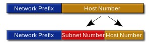

A subnet is defined by changing the bit mask of the IP address, or create subnets by “borrowing” bits from the default host bits. A subnet address includes the original classful network portion plus a subnet field also called, the extended network prefix. Due to subnet field, the mask becomes longer than default mask for address classes. In subnet mask, the network bits are represented by 1s and host bits by 0s with the result of a bit-wise logical ‘AND’ operation between the IP address and the subnet mask results in a network Address or number or subnet address. A subnet mask is only used locally but referred as a standard IP address elsewhere.
Before sending a packet, host determines if destination address is on the local network by comparing the network bits in destination address with the network bits of sender. If both are same, data transfer uses the ARP process to bind the destination IP address to the destination MAC address else, the sender forwards the data to MAC address of the default gateway which routes the packet cross different subnets.
Using a subnet mask of 255.255.255.192, an 192.168.123.0 network then becomes four networks 192.168.123.0, 192.168.123.64, 192.168.123.128 and 192.168.123.192. These four networks would have as valid host addresses
192.168.123.1-62, 192.168.123.65-126, 192.168.123.129-190 and 192.168.123.193-254
The network part is expressed in CIDR notation and written as the first address of a network, followed by a slash character (/), and ending with the bit-length of the prefix like, 192.168.1.0/24 is the prefix of network starting at given address, having 24 bits allocated for the network prefix, and the remaining 8 bits reserved for host addressing. The IPv6 address specification 2001:db8::/32 is a large network with 296 addresses, having a 32-bit routing prefix. In IPv4 the network prefix is also specified in the form of the subnet mask, which is expressed in quad-dotted decimal representation like an address. For example, 255.255.255.0 is the network mask for the 192.168.1.0/24 prefix. Another example of subnetting explains the concept –
Original Network Address & Subnet Mask: 192.168.6.0 255.255.255.0
New Subnet Mask: 255.255.255.192
Bits Borrowed: 192.168.6.11|000000
# of possible networks: 4
Each Sub-Network address increments by 64
1st Network 192.168.6.0
1st Usable 192.168.6.1
Last Usable 192.168.6.62
Broadcast 192.168.6.63
2nd Network 192.168.6.64
1st Usable 192.168.6.65
Last Usable 192.168.6.126
Broadcast 192.168.6.127
3nd Network 192.168.6.128
1st Usable 192.168.6.129
Last Usable 192.168.6.190
Broadcast 192.168.6.191
4nd Network 192.168.6.192
1st Usable 192.168.6.193
Last Usable 192.168.6.254
Broadcast 192.168.6.255
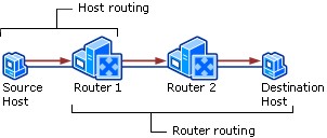
Host & Router Routing
Host Routing – Hosts actually use some simple routing logic when choosing where to send a packet. This two-step logic is as follows
- If destination IP address is in same subnet, send the packet directly to that destination host.
- If destination IP address is not in same subnet, send the packet to default gateway.
Router Routing – When a router gets a packet that is not destined for it, the router deliver it to either the destination host or to another router, as per the logic
- If destination network matches a router attached network, router forwards packet to destination by destination host’s physical address.
- If destination network is not directly attached, the router forwards packet to an intermediate router’s physical address chosen as per optimal route in the routing table.

PING – It is a utility used to test the reach ability of a host on an Internet Protocol (IP) network and to measure the round-trip time for messages sent from the originating host to a destination computer. Ping operates by sending Internet Control Message Protocol (ICMP) echo request packets to the target host and waiting for an ICMP response. In the process it measures the time from transmission to reception (round-trip time) and records any packet loss.
The ping command can be run with various command line switches to enable special operational modes, like specifying packet size used, automatic repeated operation and time stamping. Ping may be abused as a simple form of denial-of-service attack in the form of a ping flood, in which the attacker overwhelms the victim with ICMP echo request packets.
| Command | Result |
| ping <ip address> | It PINGs a remote host by IP address, succeed if the network path and the remote host are working and the PINGs are not blocked. |
| ping <host name> | It PINGs a host by name. If DNS is working, it will succeed. |
IPv6
IPv6 (Internet Protocol version 6) is a set of specifications from the Internet Engineering Task Force (IETF) that’s essentially an upgrade of IP version 4 (IPv4). The basics of IPv6 are similar to those of IPv4 — devices can use IPv6 as source and destination addresses to pass packets over a network, and tools like ping work for network testing as they do in IPv4, with some slight variations.
The most obvious improvement in IPv6 over IPv4 is that IP addresses are lengthened from 32 bits to 128 bits. This extension anticipates considerable future growth of the Internet and provides relief for what was perceived as an impending shortage of network addresses. IPv6 also supports auto-configuration to help correct most of the shortcomings in version 4, and it has integrated security and mobility features.
IPv6 features include:
- Supports source and destination addresses that are 128 bits (16 bytes) long.
- Requires IPSec support.
- Uses Flow Label field to identify packet flow for QoS handling by router.
- Allows the host to send fragments packets but not routers.
- Doesn’t include a checksum in the header.
- Uses a link-local scope all-nodes multicast address.
- Does not require manual configuration or DHCP.
- Uses host address (AAAA) resource records in DNS to map host names to IPv6 addresses.
- Uses pointer (PTR) resource records in the IP6.ARPA DNS domain to map IPv6 addresses to host names.
- Supports a 1280-byte packet size (without fragmentation).
- Moves optional data to IPv6 extension headers.
- Uses Multicast Neighbor Solicitation messages to resolve IP addresses to link-layer addresses.
- Uses Multicast Listener Discovery (MLD) messages to manage membership in local subnet groups.
- Uses ICMPv6 Router Solicitation and Router Advertisement messages to determine the IP address of the best default gateway.
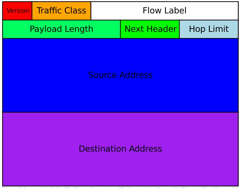
IPv6 Packet – An IPv6 packet has two parts: a header and payload.
The header consists of a fixed portion with minimal functionality required for all packets and may be followed by optional extensions to implement special features.
The fixed header occupies the first 40 octets (320 bits) of the IPv6 packet. It contains the source and destination addresses, traffic classification options, a hop counter, and the type of the optional extension or payload which follows the header. This Next Header field tells the receiver how to interpret the data which follows the header. If the packet contains options, this field contains the option type of the next option. The “Next Header” field of the last option, points to the upper-layer protocol that is carried in the packet’s payload.
Extension headers carry options that are used for special treatment of a packet in the network, e.g., for routing, fragmentation, and for security using the IPsec framework. Without special options, a payload must be less than 64KB. With a Jumbo Payload option (in a Hop-By-Hop Options extension header), the payload must be less than 4 GB. Unlike with IPv4, routers never fragment a packet. Hosts are expected to use Path MTU Discovery to make their packets small enough to reach the destination without needing to be fragmented.

IPv6 Addressing – An IPv6 address is made of 128 bits divided into eight 16-bits blocks. Each block is then converted into 4-digit Hexadecimal numbers separated by colon symbols. For example, given below is a 128 bit IPv6 address represented in binary format and divided into eight 16-bits blocks:
0010000000000001 0000000000000000 0011001000111000 1101111111100001 0000000001100011 0000000000000000 0000000000000000 1111111011111011
Each block is then converted into Hexadecimal and separated by ‘:’ symbol:
2001:0000:3238:DFE1:0063:0000:0000:FEFB
Even after converting into Hexadecimal format, IPv6 address remains long.
Transport Control Protocol (TCP)
The transport layer or layer 4 defines functions of error recovery and flow control. Both the OSI model and TCP/IP model call this layer the transport layer. The main features supported by TCP and/or UDP are
| Function | Description |
| Multiplexing using ports | Receive hosts to correct application for which the data is destined as per the port number. |
| Error recovery or reliability | Numbering and acknowledging data with sequence and acknowledgment header fields. |
| Flow control using windowing | Using window sizes to protect buffer space. |
| Connection establishment
and termination |
Initialize port numbers and Sequence and Acknowledgment fields. |
| Ordered data transfer
and data segmentation |
Segmenting bytes from upper-layer for transmission and delivery to upper-layer processes at receiving device, in same order. |
Transport Layer Protocols – TCP and UDP – Both TCP and UDP differ as TCP provides for retransmission for error recovery and avoid congestion by flow control, but UDP does not. Hence, TCP provides a wide variety of services to applications, whereas UDP does not.
UDP with few services needs fewer bytes in its header compared to TCP, resulting in fewer bytes of overhead in the network. UDP does not slow down data transfer where TCP may. Further, voice over IP (VoIP) and video over IP, do not need error recovery, so they use UDP.
Transmission Control Protocol Segment – TCP segment structure is
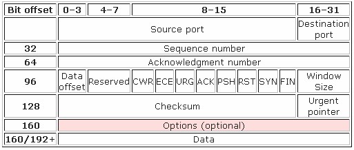

The TCP header consists of 11 fields, of which only 10 are required. The eleventh field is optional and called “options”. The details of TCP header fields are
- Source port (16 bits) – identifies sending port
- Destination port (16 bits) – identifies receiving port
- Sequence number (32 bits) – Ensure correct sequencing of the arriving data. The sequence number of the first data octet in this segment (except when SYN is present). If SYN is present the sequence number is the initial sequence number (ISN) and the first data octet is ISN+1.
- Acknowledgment number (32 bits) – Next expected TCP octet. If the ACK control bit is set this field contains the value of the next sequence number the sender of the segment is expecting to receive. Once a connection is established this is always sent.
- Data Offset (4 bits) – The number of 32 bit words in the TCP Header. This indicates where the data begins. The TCP header (even one including options) is an integral number of 32 bits long.
- Reserved (4 bits) – Reserved for future use and set to zero
- Flags (8 bits) (or Control bits) – contains 8 1-bit flags, which are
- CWR – Congestion Window Reduced (CWR) flag is set by the sending host to indicate that it received a TCP segment with the ECE flag set and had responded in congestion control mechanism
- ECE – ECN-Echo has a dual role, depending on the value of the SYN flag. It indicates – if the SYN flag is set (1), that the TCP peer is ECN capable. If the SYN flag is clear (0), that a packet with Congestion Experienced flag set (ECN=11) in IP header received during normal transmission (added to header by RFC 3168). This serves as an indication of network congestion (or impending congestion) to the TCP sender.
- URG – indicates that the urgent pointer field has a valid pointer to data that should be treated urgently and be transmitted before non-urgent data.
- ACK – is used to acknowledge the remote host’s sequence numbers, declaring that the information in the acknowledgment field is valid.
- PSH – is set on the sending side, and tells the TCP stack to flush all buffers and send any outstanding data up to and including the data that had the PSH flag set. When the receiving TCP sees the PSH flag, it too must flush its buffers and pass the information up to the application.
- RST – tells the receiving TCP stack to immediately abort the connection.
- SYN – is used in establishing a TCP connection to synchronize the sequence numbers between both endpoints.
- FIN – is used to indicate that the client will send no more data (but will continue to listen for data).
- Window (16 bits) – Number of bytes that receiver is currently willing to receive. It is also the size of the receive window, which specifies the number of window size units (in bytes) (beyond the segment identified by the sequence number in the acknowledgment field) that the sender of this segment is currently willing to receive (as per flow control and windowing)
- Checksum (16 bits) – Used for error-checking of the header and data. The checksum field is 16 bit one’s complement of the one’s complement sum of all 16 bit words in the header and text.
- Urgent pointer (16 bits) – Indicates the end of urgent data. This field is only be interpreted in segments with the URG control bit set.
- Options (Variable 0-320 bits, divisible by 32) – It’s length is determined by the data offset field. Options 0 and 1 are a single byte (8 bits) in length. The remaining options indicate the total length of the option (expressed in bytes) in the second byte.
TCP Timestamps – TCP timestamps, defined in RFC 1323, can help TCP determine in which order packets were sent. TCP timestamps are not normally aligned to the system clock and start at some random value. Many operating systems will increment the timestamp for every elapsed millisecond; however the RFC only states that the ticks should be proportional. There are two timestamp fields
- a 4-byte sender timestamp value (my timestamp)
- a 4-byte echo reply timestamp value (the most recent timestamp received from you).
Ports & Their Multiplexing – TCP and UDP both uses port multiplexing so that the computer can run many applications, like web browser, e-mail client software, an Internet VoIP application (like Skype), etc. Multiplexing enables the receiving computer to know which application to give the data to.
Multiplexing is done by assigning different port numbers to applications and adding this port number information in segment to synchronize both sender and receiver. The data from different applications operating on a network device are multiplexed at the sending device using port numbers and demultiplexed at the receiving device, again using port numbers. The two 16 bit fields in the TCP Header, Source port and Destination port identifies the port number which the application is listening at the sending device and receiving device. Since port number is a 16 bit number, the maximum possible value is 65535 ((2^16)-1). The port numbers are divided into three ranges.
- The Well Known Ports are in range of 0 – 1023 and assigned by IANA.
- The Registered Ports are in range 1024 – 49151.
- The Private Ports are in range 49152 – 65535.
Multiplexing relies on a concept called a socket which consists of
- An IP address
- A transport protocol
- A port number
Few popular TCP/IP Applications and ports are listed
| Port Number | Description |
| 20 | FTP – Data |
| 21 | FTP – Control |
| 22 | SSH Remote Login Protocol |
| 23 | Telnet |
| 25 | Simple Mail Transfer Protocol (SMTP) |
| 80 | HTTP |
| 109 | POP2 |
| 110 | POP3 |
| 115 | Simple File Transfer Protocol (SFTP) |
| 119 | Newsgroup (NNTP) |
| 137 | NetBIOS Name Service |
| 139 | NetBIOS Datagram Service |
| 143 | Interim Mail Access Protocol (IMAP) |
| 150 | NetBIOS Session Service |
| 161 | SNMP |
| 179 | Border Gateway Protocol (BGP) |
| 194 | Internet Relay Chat (IRC) |
| 389 | Lightweight Directory Access Protocol (LDAP) |
| 396 | Novell Netware over IP |
| 443 | HTTPS |
| 444 | Simple Network Paging Protocol (SNPP) |
| 445 | Microsoft-DS |
| 546 | DHCP Client |
| 547 | DHCP Server |
TCP Error Recovery – TCP provides for reliable data transfer or reliability or error recovery by numbering data bytes using the sequence and acknowledgment fields in the header. TCP was designed to recover from node or line failures where the network propagates routing table changes to all router nodes but, TCP is slow to initiate recovery.
TCP treats the data as a stream of bytes. It logically assigns a sequence number to each byte. The TCP packet has a header says, “This packet starts with byte 379642 and contains 200 bytes of data.” The receiver can detect missing or incorrectly sequenced packets. TCP acknowledges data that has been received and retransmits data that has been lost. The error recovery is done end-to-end between the client and server. For example a server sending 1000 bytes of data to client and a sequence number 1000 is used in the TCP header. The server sends another 1000 bytes of data with sequence number 2000 and yet another 1000 bytes of data with sequence number 3000. Next the client sends acknowledgement to the server for successfully receiving of 3000 bytes. The 4000 in the acknowledgement field implies the next byte to be received.
A fundamental notion in the design is that every octet of data sent over a TCP connection has a sequence number. Since every octet is sequenced, each of them can be acknowledged. The acknowledgment mechanism employed is cumulative so that an acknowledgment of sequence number X indicates that all octets up to but not including X have been received. This mechanism allows for straight-forward duplicate detection in the presence of retransmission. Numbering of octets within a segment is that the first data octet immediately following the header is the lowest numbered, and the following octets are numbered consecutively.
It is essential to remember that the actual sequence number space is finite, though very large. This space ranges from 0 to 2**32 – 1. Since the space is finite, all arithmetic dealing with sequence numbers must be performed modulo 2**32. This unsigned arithmetic preserves the relationship of sequence numbers as they cycle from 2**32 – 1 to 0 again. There are some subtleties to computer modulo arithmetic, so great care should be taken in programming the comparison of such values.
TCP Sliding Window Protocol – A sliding window algorithm places a buffer between the application program and the network data flow. For TCP, the buffer is usually in the operating system kernel.
Data received from the network is stored in the buffer, from whence the application can read at its own pace. As the application reads data, buffer space is freed up to accept more input from the network. The window is the amount of data that can be “read ahead” – the size of the buffer, less the amount of valid data stored in it. Window announcements are used to inform the remote host of the current window size.
If the local application can’t process data fast enough, the window size will drop to zero and the remote host will stop sending data. After the local application has processed some of the queued data, the window size rises, and the remote host starts transmitting again.
On the other hand, if the local application can process data at the rate it’s being transferred, sliding window still gives us an advantage. If the window size is larger than the packet size, then multiple packets can be outstanding in the network, since the sender knows that buffer space is available on the receiver to hold all of them. Ideally, a steady-state condition can be reached where a series of packets (in the forward direction) and window announcements (in the reverse direction) are constantly in transit. As each new window announcement is received by the sender, more data packets are transmitted. As the application reads data from the buffer (remember, we’re assuming the application can keep up with the network), more window announcements are generated. Keeping a series of data packets in transit ensures the efficient use of network resources.
Flow Control Using Windowing – Consider a high CPU speed host transmitting data to a slow CPU speed. Obviously, the high CPU speed host will be able to drown the slower one with data. Thus, flow control is needed to pace the data transfer at an acceptable speed.
Request/reply flow control requires each data packet to be acknowledge by the remote host before the next packet is sent. Sliding window algorithms, used by TCP, permit multiple data packets to be in simultaneous transit, making more efficient use of network bandwidth. Finally, Internet’s Unreliable Delivery Model allows packets to be discarded if network resources are not available, and demands that protocols make provisions for retransmission.
TCP implements flow control by using the sequence, acknowledgment and window fields in the header. The window field specify the maximum number of unacknowledged bytes which are allowed to be outstanding at any instant in time. The window starts small and then grows until errors occur thus also called a dynamic window. As the actual sequence and acknowledgment numbers grow over time, the window is also called a sliding window. The working is done as
- Dropping the segments as failed acknowledgments alert sender to slow down or stop sending.
- Setting a smaller window size as each TCP acknowledgement contains a field called window Size, which specifies the number of bytes that the receiving TCP is currently prepared to receive. Setting the window size to a smaller value allows less data to be processed in the future. More specific, the widow size is the number of data segments the sender is allowed to send before getting acknowledgment from the receiver. A smaller window size means the sending TCP has to wait for more acknowledgement in order to send the same amount of data, as a result, the time cause by these extra acknowledgment slows down the data transmission process.
If an acknowledgment is received before window is completed, a new window start and the sender continues sending data until the current window is completes. Windowing mechanism is also called as positive acknowledgment and retransmission or PAR.
Data Segmentation and Ordered Data Transfer – Different data-link protocols have different limit on maximum transmission unit ( MTU) that can be sent inside a data link layer frame. Hence, MTU is size of largest layer 3 packet fitted in a frame’s data field like for Ethernet, IP packet is less than 1500 bytes hence, TCP segments data into smaller pieces, called segments usually 1460-byte blocks and assigns sequence number to them. TCP at receiver, reassembles the segments and also recovers lost segments.
During transmission, the segments may be received out of order thus, TCP at receiver end performs ordered data transfer by reassembling the data into original order like if segments arrive with the sequence numbers 1500, 3500, and 2500, each with 1000 bytes of data, the receiver can reorder them without retransmission. The TCP header and the data field together are called a TCP segment or L4 PDU as TCP is a Layer 4 protocol.
TCP Connection Establish and Terminate – Connection establishment refer to process of initializing sequence and acknowledgment fields and agreeing on the port number to use. It is an three-way process and connection establishment uses 2 bits in flag fields of TCP header called the SYN and ACK flags. SYN means “Synchronize the sequence numbers,” used to initialize sequence numbers and the ACK field means “The Acknowledgment field is valid in this header” for acknowledging the sequence received. For a connection to be established, the two end stations must synchronize on each other’s initial TCP sequence numbers. This initial exchange ensures that lost data can be recovered. The steps for synchronization are
- A –> B SYN – My sequence number is X
- A <– B ACK – Your sequence number is X -1; expect X + 1 next
- A <– B SYN – My sequence number is Y
- A –> B ACK – Your sequence number is Y -1; expect Y + 1 next
Because step 2 and 3 are combined into one message, it is called a three-way handshake, as
- SYN: The active open is performed by the client sending a SYN to the server. The client sets the segment’s sequence number to a random value A.
- SYN-ACK: In response, the server replies with a SYN-ACK. The acknowledgment number is set to one more than the received sequence number i.e. A+1, and the sequence number that the server chooses for the packet is another random number, B.
- ACK: Finally, the client sends an ACK back to the server. The sequence number is set to the received acknowledgement value i.e. A+1, and the acknowledgement number is set to one more than the received sequence number i.e. B+1.
TCP connection termination is a four- step process which uses an additional flag, called FIN bit. (or “finished”). The connection termination phase uses a four-way handshake, with each side of the connection terminating independently. When an endpoint wishes to stop its half of the connection, it transmits a FIN packet, which the other end acknowledges with an ACK. Therefore, a typical tear-down requires a pair of FIN and ACK segments from each TCP endpoint. After the side that sent the first FIN has responded with the final ACK, it waits for a timeout before finally closing the connection, during which time the local port is unavailable for new connections; this prevents confusion due to delayed packets being delivered during subsequent connections.
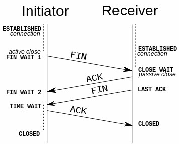

It is also possible to terminate the connection by a 3-way handshake, when host A sends a FIN and host B replies with a FIN & ACK (merely combines 2 steps into one) and host A replies with an ACK.
TCP establishes and terminates connections between the endpoints, whereas UDP does not hence, depending upon the connection management protocols are
- Connection-oriented protocol- A protocol that requires an exchange of messages before data transfer begins or that has a required pre-established correlation between two endpoints
- Connectionless protocol- A protocol that does not require an exchange of messages and that does not require a pre-established correlation between two endpoints
UDP (User Datagram Protocol) – UDP is a connectionless and unacknowledged protocol which transmits messages with “best effort” without any check for the delivery for segments. UDP depends on upper-layer protocols for reliability. In a network, broadcast and unicast messages are carried by UDP and protocols that use UDP include TFTP, SNMP, NFS and DNS. The UDP header consists of only 4 fields with two being optional (highlighted) as
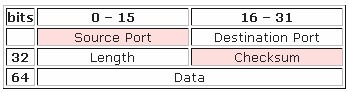

- Source port – ID of the calling port.
- Destination port – ID of the called port.
- Length — Length of UDP header and UDP data.
- Checksum — Calculated checksum of the header and data fields.
UDP has no reordering or recovery mechanism. However, UDP provides data transfer and multiplexing using port numbers as TCP but, UDP uses lesser bytes of overhead and processing than TCP. Hence, applications using UDP should be tolerant of the lost data. VoIP uses UDP as time to discover and re-transmit lost voice packet adds too much delay. Similarly any DNS request failure will be retried.
tcpdump
tcpdump is a common packet analyzer that runs under the command line. It allows the user to display TCP/IP and other packets being transmitted or received over a network to which the computer is attached. Distributed under the BSD license.
Tcpdump prints out a description of the contents of packets on a network interface that match the boolean expression; the description is preceded by a time stamp, printed, by default, as hours, minutes, seconds, and fractions of a second since midnight. It can also be run with the -w flag, which causes it to save the packet data to a file for later analysis, and/or with the -r flag, which causes it to read from a saved packet file rather than to read packets from a network interface. It can also be run with the -V flag, which causes it to read a list of saved packet files. In all cases, only packets that match expression will be processed by tcpdump.
When tcpdump finishes capturing packets, it will report counts of:
- packets “captured” (this is the number of packets that tcpdump has received and processed);
- packets “received by filter” (the meaning of this depends on the OS on which you’re running tcpdump, and possibly on the way the OS was configured – if a filter was specified on the command line, on some OSes it counts packets regardless of whether they were matched by the filter expression and, even if they were matched by the filter expression, regardless of whether tcpdump has read and processed them yet, on other OSes it counts only packets that were matched by the filter expression regardless of whether tcpdump has read and processed them yet, and on other OSes it counts only packets that were matched by the filter expression and were processed by tcpdump);
- packets “dropped by kernel” (this is the number of packets that were dropped, due to a lack of buffer space, by the packet capture mechanism in the OS on which tcpdump is running, if the OS reports that information to applications; if not, it will be reported as 0).
Syntax
tcpdump [ -AbdDefhHIJKlLnNOpqStuUvxX# ] [ -B buffer_size ] [ -c count ] [ -C file_size ] [ -G rotate_seconds ] [ -F file ] [ -i interface ] [ -j tstamp_type ] [ -m module ] [ -M secret ] [ –number ] [ -Q in|out|inout ] [ -r file ] [ -V file ] [ -s snaplen ] [ -T type ] [ -w file ] [ -W filecount ] [ -E spi@ipaddr algo:secret,… ] [ -y datalinktype ] [ -z postrotate-command ] [ -Z user ] [ –time-stamp-precision=tstamp_precision ] [ –immediate-mode ] [ –version ] [ expression ]
OPTIONS
- -A – Print each packet (minus its link level header) in ASCII. Handy for capturing web pages.
- -b – Print the AS number in BGP packets in ASDOT notation rather than ASPLAIN notation.
- -B buffer_size or –buffer-size=buffer_size – Set the operating system capture buffer size to buffer_size, in units of KiB (1024 bytes).
- -c count – Exit after receiving count packets.
- -C file_size – Before writing a raw packet to a savefile, check whether the file is currently larger than file_size and, if so, close the current savefile and open a new one. Savefiles after the first savefile will have the name specified with the -w flag, with a number after it, starting at 1 and continuing upward. The units of file_size are millions of bytes (1,000,000 bytes, not 1,048,576 bytes).
- -d – Dump the compiled packet-matching code in a human readable form to standard output and stop.
- -dd – Dump packet-matching code as a C program fragment.
- -ddd – Dump packet-matching code as decimal numbers (preceded with a count).
- -D or –list-interfaces – Print the list of the network interfaces available on the system and on which tcpdump can capture packets. For each network interface, a number and an interface name, possibly followed by a text description of the interface, is printed. The interface name or the number can be supplied to the -i flag to specify an interface on which to capture. This can be useful on systems that don’t have a command to list them (e.g., Windows systems, or UNIX systems lacking ifconfig -a); the number can be useful on Windows 2000 and later systems, where the interface name is a somewhat complex string. The -D flag will not be supported if tcpdump was built with an older version of libpcap that lacks the pcap_findalldevs() function.
- -e – Print the link-level header on each dump line. This can be used, for example, to print MAC layer addresses for protocols such as Ethernet and IEEE 802.11.
- -E – Use spi@ipaddr algo:secret for decrypting IPsec ESP packets that are addressed to addr and contain Security Parameter Index value spi. This combination may be repeated with comma or newline separation.
- -f – Print `foreign’ IPv4 addresses numerically rather than symbolically (this option is intended to get around serious brain damage in Sun’s NIS server — usually it hangs forever translating non-local internet numbers).
- -F file – Use file as input for the filter expression. An additional expression given on the command line is ignored.
- -G rotate_seconds – If specified, rotates the dump file specified with the -w option every rotate_seconds seconds. Savefiles will have the name specified by -w which should include a time format as defined by strftime(3). If no time format is specified, each new file will overwrite the previous.
- -h or –help – Print the tcpdump and libpcap version strings, print a usage message, and exit.
- –version – Print the tcpdump and libpcap version strings and exit.
- -H – Attempt to detect 802.11s draft mesh headers.
- -i interface or –interface=interface – Listen on interface. If unspecified, tcpdump searches the system interface list for the lowest numbered, configured up interface (excluding loopback), which may turn out to be, for example, “eth0”.
- -I or –monitor-mode – Put the interface in “monitor mode”; this is supported only on IEEE 802.11 Wi-Fi interfaces, and supported only on some operating systems.
- –immediate-mode – Capture in “immediate mode”. In this mode, packets are delivered to tcpdump as soon as they arrive, rather than being buffered for efficiency. This is the default when printing packets rather than saving packets to a “savefile” if the packets are being printed to a terminal rather than to a file or pipe.
- -j tstamp_type or –time-stamp-type=tstamp_type – Set the time stamp type for the capture to tstamp_type. The names to use for the time stamp types are given in pcap-tstamp(7); not all the types listed there will necessarily be valid for any given interface.
- -J or –list-time-stamp-types – List the supported time stamp types for the interface and exit. If the time stamp type cannot be set for the interface, no time stamp types are listed.
- –time-stamp-precision=tstamp_precision – When capturing, set the time stamp precision for the capture to tstamp_precision. Note that availability of high precision time stamps (nanoseconds) and their actual accuracy is platform and hardware dependent. Also note that when writing captures made with nanosecond accuracy to a savefile, the time stamps are written with nanosecond resolution, and the file is written with a different magic number, to indicate that the time stamps are in seconds and nanoseconds; not all programs that read pcap savefiles will be able to read those captures.
- -K or –dont-verify-checksums – Don’t attempt to verify IP, TCP, or UDP checksums. This is useful for interfaces that perform some or all of those checksum calculation in hardware; otherwise, all outgoing TCP checksums will be flagged as bad.
- -l – Make stdout line buffered. Useful if you want to see the data while capturing it.
- -L or –list-data-link-types – List the known data link types for the interface, in the specified mode, and exit. The list of known data link types may be dependent on the specified mode; for example, on some platforms, a Wi-Fi interface might support one set of data link types when not in monitor mode (for example, it might support only fake Ethernet headers, or might support 802.11 headers but not support 802.11 headers with radio information) and another set of data link types when in monitor mode (for example, it might support 802.11 headers, or 802.11 headers with radio information, only in monitor mode).
- -m module – Load SMI MIB module definitions from file module. This option can be used several times to load several MIB modules into tcpdump.
- -M secret – Use secret as a shared secret for validating the digests found in TCP segments with the TCP-MD5 option (RFC 2385), if present.
- -n – Don’t convert addresses (i.e., host addresses, port numbers, etc.) to names.
- -N – Don’t print domain name qualification of host names. E.g., if you give this flag then tcpdump will print “nic” instead of “nic.ddn.mil”.
- -# or –number – Print an optional packet number at the beginning of the line.
- -O or –no-optimize – Do not run the packet-matching code optimizer. This is useful only if you suspect a bug in the optimizer.
- -p or –no-promiscuous-mode – Don’t put the interface into promiscuous mode. Note that the interface might be in promiscuous mode for some other reason; hence, `-p’ cannot be used as an abbreviation for `ether host {local-hw-addr} or ether broadcast’.
- -Q direction or –direction=direction – Choose send/receive direction direction for which packets should be captured. Possible values are `in’, `out’ and `inout’. Not available on all platforms.
- -q – Quick (quiet?) output. Print less protocol information so output lines are shorter.
- -r file – Read packets from file (which was created with the -w option or by other tools that write pcap or pcap-ng files). Standard input is used if file is “-”.
- -S or –absolute-tcp-sequence-numbers – Print absolute, rather than relative, TCP sequence numbers.
- -s snaplen or –snapshot-length=snaplen – Snarf snaplen bytes of data from each packet rather than the default of 262144 bytes. Packets truncated because of a limited snapshot are indicated in the output with “[|proto]”, where proto is the name of the protocol level at which the truncation has occurred. Note that taking larger snapshots both increases the amount of time it takes to process packets and, effectively, decreases the amount of packet buffering. This may cause packets to be lost. You should limit snaplen to the smallest number that will capture the protocol information you’re interested in. Setting snaplen to 0 sets it to the default of 262144, for backwards compatibility with recent older versions of tcpdump.
- -T type – Force packets selected by “expression” to be interpreted the specified type. Currently known types are aodv (Ad-hoc On-demand Distance Vector protocol), carp (Common Address Redundancy Protocol), cnfp (Cisco NetFlow protocol), lmp (Link Management Protocol), pgm (Pragmatic General Multicast), pgm_zmtp1 (ZMTP/1.0 inside PGM/EPGM), radius (RADIUS), rpc (Remote Procedure Call), rtp (Real-Time Applications protocol), rtcp (Real-Time Applications control protocol), snmp (Simple Network Management Protocol), tftp (Trivial File Transfer Protocol), vat (Visual Audio Tool), wb (distributed White Board), zmtp1 (ZeroMQ Message Transport Protocol 1.0) and vxlan (Virtual eXtensible Local Area Network).
- -t – Don’t print a timestamp on each dump line.
- -tt – Print the timestamp, as seconds since January 1, 1970, 00:00:00, UTC, and fractions of a second since that time, on each dump line.
- -u – Print undecoded NFS handles.
- -U or –packet-buffered – If the -w option is not specified, make the printed packet output “packet-buffered”; i.e., as the description of the contents of each packet is printed, it will be written to the standard output, rather than, when not writing to a terminal, being written only when the output buffer fills.
- -v – When parsing and printing, produce (slightly more) verbose output. For example, the time to live, identification, total length and options in an IP packet are printed. Also enables additional packet integrity checks such as verifying the IP and ICMP header checksum.
- -V file – Read a list of filenames from file. Standard input is used if file is “-”.
- -w file – Write the raw packets to file rather than parsing and printing them out. They can later be printed with the -r option. Standard output is used if file is “-”.
- -W – Used in conjunction with the -C option, this will limit the number of files created to the specified number, and begin overwriting files from the beginning, thus creating a ‘rotating’ buffer. In addition, it will name the files with enough leading 0s to support the maximum number of files, allowing them to sort correctly.
- -x – When parsing and printing, in addition to printing the headers of each packet, print the data of each packet (minus its link level header) in hex. The smaller of the entire packet or snaplen bytes will be printed. Note that this is the entire link-layer packet, so for link layers that pad (e.g. Ethernet), the padding bytes will also be printed when the higher layer packet is shorter than the required padding.
- -xx – When parsing and printing, in addition to printing the headers of each packet, print the data of each packet, including its link level header, in hex.
- -X – When parsing and printing, in addition to printing the headers of each packet, print the data of each packet (minus its link level header) in hex and ASCII. This is very handy for analysing new protocols.
- -XX – When parsing and printing, in addition to printing the headers of each packet, print the data of each packet, including its link level header, in hex and ASCII.
- -y datalinktype or –linktype=datalinktype – Set the data link type to use while capturing packets to datalinktype.
- -z postrotate-command – Used in conjunction with the -C or -G options, this will make tcpdump run ” postrotate-command file ” where file is the savefile being closed after each rotation. For example, specifying -z gzip or -z bzip2 will compress each savefile using gzip or bzip2.
- -Z user or –relinquish-privileges=user – If tcpdump is running as root, after opening the capture device or input savefile, but before opening any savefiles for output, change the user ID to user and the group ID to the primary group of user. This behavior can also be enabled by default at compile time.
- expression – selects which packets will be dumped. If no expression is given, all packets on the net will be dumped. Otherwise, only packets for which expression is `true’ will be dumped. The expression argument can be passed to tcpdump as either a single Shell argument, or as multiple Shell arguments, whichever is more convenient. Generally, if the expression contains Shell metacharacters, such as backslashes used to escape protocol names, it is easier to pass it as a single, quoted argument rather than to escape the Shell metacharacters. Multiple arguments are concatenated with spaces before being parsed.
Examples
- To print all packets arriving at or departing from sundown – tcpdump host sundown
- To print traffic between helios and either hot or ace – tcpdump host helios and \( hot or ace \)
- To print all IP packets between ace and any host except helios – tcpdump ip host ace and not helios
- To print all traffic between local hosts and hosts at Berkeley – tcpdump net ucb-ether
- To print all ftp traffic through internet gateway snup: (note that the expression is quoted to prevent the shell from (mis-)interpreting the parentheses) – tcpdump ‘gateway snup and (port ftp or ftp-data)’
- To print traffic neither sourced from nor destined for local hosts (if you gateway to one other net, this stuff should never make it onto your local net) – tcpdump ip and not net localnet
- To print the start and end packets (the SYN and FIN packets) of each TCP conversation that involves a non-local host – tcpdump ‘tcp[tcpflags] & (tcp-syn|tcp-fin) != 0 and not src and dst net localnet’
- To print all IPv4 HTTP packets to and from port 80, i.e. print only packets that contain data, not, for example, SYN and FIN packets and ACK-only packets – tcpdump ‘tcp port 80 and (((ip[2:2] – ((ip[0]&0xf)<<2)) – ((tcp[12]&0xf0)>>2)) != 0)’
- To print IP packets longer than 576 bytes sent through gateway snup – tcpdump ‘gateway snup and ip[2:2] > 576’
- To print IP broadcast or multicast packets that were not sent via Ethernet broadcast or multicast tcpdump ‘ether[0] & 1 = 0 and ip[16] >= 224’
- To print all ICMP packets that are not echo requests/replies (i.e., not ping packets) – tcpdump ‘icmp[icmptype] != icmp-echo and icmp[icmptype] != icmp-echoreply’
Apply for Linux Administration Certification Now!!
http://www.vskills.in/certification/Certified-Linux-Administrator