Network Layer Functions
OSI network layer has following functions which include
- Logical addressing – Sending the data packet from one network to another network requires logical addressing. It helps to distinguish source and destination systems. Network layer adds header to data coming from upper layers and include logical address of sender and receiver. Every host in the network must have a unique address that determines where it is. This address is normally assigned from a hierarchical system.
- Routing – As networks are divided into subnetworks and connect to other networks for wide-area communications, networks use gateways or routers to route packets to their final destination. It is also called as the process of forwarding packets (Layer 3 PDUs)
- Routing protocol – A protocol used by routers to learn dynamically about addresses in a network, for decision making during routing or forwarding process.
IP Packets
IP packets are composed of a header and payload as shown
IP Header
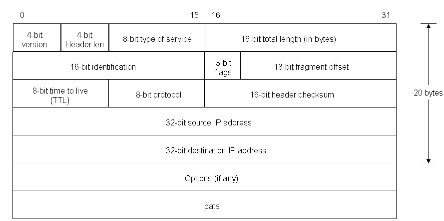
The IPv4 packet header consists of
- 4 bits that contain the version, that specifies if it’s an IPv4 or IPv6 packet,
- 4 bits that contain the Internet Header Length, which is the length of the header in multiples of 4 bytes (e.g., 5 means 20 bytes).
- 8 bits that contain the Type of Service, also referred to as Quality of Service (QoS), which describes what priority the packet should have,
- 16 bits that contain the length of the packet in bytes,
- 16 bits that contain an identification tag to help reconstruct the packet from several fragments,
- 3 bits. The first contains a zero, followed by a flag that says whether the packet is allowed to be fragmented or not (DF or Don’t fragment), and a flag to state whether more fragments of a packet follow (MF or More Fragments)
- 13 bits that contain the fragment offset, a field to identify position of fragment within original packet
- 8 bits that contain the Time to live (TTL), which is the number of hops (router, computer or device along a network) the packet is allowed to pass before it dies (for example, a packet with a TTL of 16 will be allowed to go across 16 routers to get to its destination before it is discarded),
- 8 bits that contain the protocol (TCP, UDP, ICMP, etc.)
- 16 bits that contain the Header Checksum, a number used in error detection,
- 32 bits that contain the source IP address,
- 32 bits that contain the destination address.
After those 160 bits, optional flags can be added of varied length, which can change as per protocol used, then data that packet carries is added. An IP packet has no trailer. However, an IP packet is often carried as the payload inside an Ethernet frame, which has its own header and trailer.
IP Routing
Data packet is routed from source to destination by passing through one or more routers and networks. The IP Routing protocols enable routers to build up a forwarding table to relate an final destination address with next hop addresses. Various protocols used in routing are BGP (Border Gateway Protocol), IS-IS (Intermediate System – Intermediate System), OSPF (Open Shortest Path First) and RIP (Routing Information Protocol).
IP routing is done on a hop-by-hop basis. IP does not know the complete route to any destination (except directly connected). IP routing provides the IP address of the next-hop router to which the data is sent and the next-hop router is assumed to be closer to destination. IP routing performs the following actions
- Search the routing table for an entry that matches the complete destination IP address (matching network ID and host ID). If found, send the packet to the indicated next-hop router or to the directly connected interface.
- Search the routing table for an entry that matches just the destination network ID. If found, send the packet to the indicated next-hop router or to the directly connected interface. All the hosts on the destination network can be handled with this single routing table entry.
- Search the routing table for an entry labeled “default.” If found, send the packet to the indicated next-hop router.
If none of the steps works, the datagram is undeliverable. If the undeliverable datagram was generated on this host, a “host unreachable” or “network unreachable” error is normally returned to the application that generated the datagram. Each entry in routing table has
- Specification of which network interface the datagram should be passed to for transmission.
- Destination IP address. It is either a host address or network address, as specified by the flag field. A host address with a nonzero host ID identifies one particular host, while a network address has a host ID of 0 and identifies all the hosts on that network.
- IP address of a next-hop router or directly connected network. The next-hop router is not the final destination, but it forwards data to the final destination.
- One flag specifies whether the destination IP address is the address of a network or the address of a host. Another flag says whether the next-hop router field is really a next-hop router or a directly connected interface.
IP routing protocols load routing tables with valid, loop-free routes and involves functions as
- Placing the best route, if more than one route to a subnet is available.
- Removing invalid routes from the routing table.
- Dynamically learn and load routing table for a route to all subnets in the
- Replace lost routes, quickly with best available route, also called convergence time.
- Preventing routing loops.
Every routing protocols publicizes it’s routes as
- Add a route for each subnet directly connected to it.
- Update neighbor router about all directly connected and learned routes.
- Add new routes from neighbors
IP Addressing
An IP address is a 32 bit binary number, looks like the following
00000100 10000000 00000011 00000001
It is divided into four 8-bit chunks, called octet, and represented into decimal number for humans to understand like 4.128.3.1 An IP address consists of two parts
- The leftmost bits specify the network address component, called network ID.
- The rightmost bits specify the host address components, called host ID.
Hosts on a network can communicate with devices in the same network by MAC address but for different networks, a router to move data is needed. Each LAN has a unique network ID and all hosts on that network have same network ID but different host ID. A network ID enables a router to put a packet onto the correct network segment. To decide which network is correct, the router looks up a routing table, which is a table contains entries for network addresses (network ID + all host bits set to 0). Each network interface uses a unique IP address.
A, B, and C Classes of Networks
IP addresses are broken into classes to accommodate different sizes of networks as
- Class A (1-126)- It supports extremely large networks and uses only first octet for the network address and rest three octets for host addresses. The first bit of a Class A address is always 0 but, the lowest number represented is 00000000 (decimal 0), and highest number is 01111111 (decimal 127) both are reserved and cannot be used as a network address. Any address start with 127 is reserved for loopback.
- Class B (128-191)- It supports middle-sized and large-sized networks with first two octets for network address and rest two octets for host addresses. The first two bits of a Class B address is binary number 10; thus, the lowest number represented is 10000000 (decimal 128) and highest number is 1011111 (decimal 191).
- Class C (192-223)- It supports small-sized networks with first three octets for network address and remaining one octet for host addresses. The first three bits of a Class C address is binary number 110 thus, lowest number represented is 11000000 (decimal 192), and the highest number is 11011111 (decimal 223).
- Class D- 224-239 is reserved for multicasting, for a single station to simultaneously transmit a datagrams to multiple recipients. It’s first four bits is binary number 1110.
- Class E- 240-255 is experimental addresses, reserved by the IETF for its research.
The block at the beginning and end of each class is called network address and broadcast address, respectively. These two special IP addresses are reserved and detailed as
- Network address- It has all host bits set to 0 to identify the network itself and cannot be assigned like 46.0.0.0 is the network address of the network containing the host 46.4.64.21.
- Broadcast address- It has all host bits set to 1 and used to send data to all the devices on a network like 46.255.255.255 is the broadcast address of network with host 46.4.64.21. Routers will forward broadcast packets on all interfaces but usually routers disable broadcast-forwarding.
The list of the Class A, B, C, D, E IP address is summarized as
| Class | Leading bits | Start | End | Network Bits | Host Bits |
| A | 0.0.0.0 | 127.255.255.255 | 8 | 24 | |
| B | 10 | 128.0.0.0 | 191.255.255.255 | 16 | 16 |
| C | 110 | 192.0.0.0 | 223.255.255.255 | 24 | 8 |
| D | 1110 | 224.0.0.0 | 239.255.255.255 |
The Internet Corporation for Assigned Network Numbers (ICANN, www.icann.org) is in charge for universal IP address assignment and ICANN, assigns regional authority to other cooperating organizations.
Transmission Control Protocol
TCP is a connection-oriented, reliable protocol. TCP must establish a connection (a virtual circuit) between both ends user applications before data transfer. The services provided by TCP is running in host computers at either end but, not in the network. Hence, TCP protocol manages end-to-end connections. TCP is defined in RFC 793 and accomplishes the following functions
- Segmenting a message passed down from the session layer into multiple segments
- Adding sequence number to each segment for ordering.
- Verifying each segment passed up from the network layer at destination.
- Reassembling received segments into a message
- Passing the message up to the session layer.
Irrespective of location of end points, TCP performs its functions the same way. TCP segment structure is
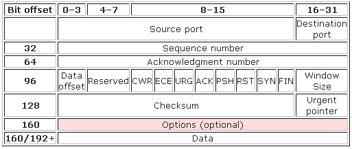
The TCP header consists of 11 fields, of which only 10 are required. The eleventh field is optional and called “options”. The details of TCP header fields are
- Source port (16 bits) – identifies sending port
- Destination port (16 bits) – identifies receiving port
- Sequence number (32 bits) – Ensure correct sequencing of the arriving data
- Acknowledgment number (32 bits) – Next expected TCP octet.
- Reserved (4 bits) – Reserved for future use and set to zero
- Flags (8 bits) (or Control bits) – contains 8 1-bit flags
- Window (16 bits) – Number of bytes that receiver is currently willing to receive
- Checksum (16 bits) – Used for error-checking of the header and data
- Urgent pointer (16 bits) – Indicates the end of urgent data
- Options (Variable 0-320 bits, divisible by 32) – It’s length is determined by the data offset field. Options 0 and 1 are a single byte (8 bits) in length. The remaining options indicate the total length of the option (expressed in bytes) in the second byte.
Ports & Their Multiplexing
TCP and UDP both uses port multiplexing so that the computer can run many applications, like web browser, e-mail client software, an Internet VoIP application (like Skype), etc. Multiplexing enables the receiving computer to know which application to give the data to.
Multiplexing is done by assigning different port numbers to applications and adding this port number information in segment to synchronize both sender and receiver. The data from different applications operating on a network device are multiplexed at the sending device using port numbers and demultiplexed at the receiving device, again using port numbers. The two 16 bit fields in the TCP Header, Source port and Destination port identifies the port number which the application is listening at the sending device and receiving device. Since port number is a 16 bit number, the maximum possible value is 65535 ((2^16)-1). The port numbers are divided into three ranges.
- The Well Known Ports are in range of 0 – 1023 and assigned by IANA.
- The Registered Ports are in range 1024 – 49151.
- The Private Ports are in range 49152 – 65535.
Multiplexing relies on a concept called a socket which consists of
- An IP address
- A transport protocol
- A port number
Few popular TCP/IP Applications and ports are listed
| Port Number | Description |
| 20 | FTP – Data |
| 21 | FTP – Control |
| 22 | SSH Remote Login Protocol |
| 23 | Telnet |
| 25 | Simple Mail Transfer Protocol (SMTP) |
| 80 | HTTP |
| 109 | POP2 |
| 110 | POP3 |
| 115 | Simple File Transfer Protocol (SFTP) |
| 119 | Newsgroup (NNTP) |
| 137 | NetBIOS Name Service |
| 139 | NetBIOS Datagram Service |
| 143 | Interim Mail Access Protocol (IMAP) |
| 150 | NetBIOS Session Service |
| 161 | SNMP |
| 179 | Border Gateway Protocol (BGP) |
| 194 | Internet Relay Chat (IRC) |
| 389 | Lightweight Directory Access Protocol (LDAP) |
| 396 | Novell Netware over IP |
| 443 | HTTPS |
| 444 | Simple Network Paging Protocol (SNPP) |
| 445 | Microsoft-DS |
| 546 | DHCP Client |
| 547 | DHCP Server |
TCP Error Recovery, Flow Control and Data Segmentation
Error Recovery – TCP provides for reliable data transfer or reliability or error recovery by numbering data bytes using the sequence and acknowledgment fields in the header. TCP was designed to recover from node or line failures where the network propagates routing table changes to all router nodes but, TCP is slow to initiate recovery.
TCP treats the data as a stream of bytes. It logically assigns a sequence number to each byte. The TCP packet has a header says, “This packet starts with byte 379642 and contains 200 bytes of data.” The receiver can detect missing or incorrectly sequenced packets. TCP acknowledges data that has been received and retransmits data that has been lost. The error recovery is done end-to-end between the client and server. For example a server sending 1000 bytes of data to client and a sequence number 1000 is used in the TCP header. The server sends another 1000 bytes of data with sequence number 2000 and yet another 1000 bytes of data with sequence number 3000. Next the client sends acknowledgement to the server for successfully receiving of 3000 bytes. The 4000 in the acknowledgement field implies the next byte to be received.
Flow Control Using Windowing – TCP implements flow control by using the sequence, acknowledgment and window fields in the header. The window field specify the maximum number of unacknowledged bytes which are allowed to be outstanding at any instant in time. The window starts small and then grows until errors occur thus also called a dynamic window. As the actual sequence and acknowledgment numbers grow over time, the window is also called a sliding window. The working is done as
- Dropping the segments as failed acknowledgments alert sender to slow down or stop sending.
- Setting a smaller window size as each TCP acknowledgement contains a field called window Size, which specifies the number of bytes that the receiving TCP is currently prepared to receive. Setting the window size to a smaller value allows less data to be processed in the future. More specific, the widow size is the number of data segments the sender is allowed to send before getting acknowledgment from the receiver. A smaller window size means the sending TCP has to wait for more acknowledgement in order to send the same amount of data, as a result, the time cause by these extra acknowledgment slows down the data transmission process.
If an acknowledgment is received before window is completed, a new window start and the sender continues sending data until the current window is completes. Windowing mechanism is also called as positive acknowledgment and retransmission or PAR.
Data Segmentation and Ordered Data Transfer – Different data-link protocols have different limit on maximum transmission unit ( MTU) that can be sent inside a data link layer frame. Hence, MTU is size of largest layer 3 packet fitted in a frame’s data field like for Ethernet, IP packet is less than 1500 bytes hence, TCP segments data into smaller pieces, called segments usually 1460-byte blocks and assigns sequence number to them. TCP at receiver, reassembles the segments and also recovers lost segments.
During transmission, the segments may be received out of order thus, TCP at receiver end performs ordered data transfer by reassembling the data into original order like if segments arrive with the sequence numbers 1500, 3500, and 2500, each with 1000 bytes of data, the receiver can reorder them without retransmission. The TCP header and the data field together are called a TCP segment or L4 PDU as TCP is a Layer 4 protocol.
TCP Connection Establish and Terminate
Connection establishment refer to process of initializing sequence and acknowledgment fields and agreeing on the port number to use. It is an three-way process and connection establishment uses 2 bits in flag fields of TCP header called the SYN and ACK flags. SYN means “Synchronize the sequence numbers,” used to initialize sequence numbers and the ACK field means “The Acknowledgment field is valid in this header” for acknowledging the sequence received. For a connection to be established, the two end stations must synchronize on each other’s initial TCP sequence numbers. This initial exchange ensures that lost data can be recovered. The steps for synchronization are
- A –> B SYN – My sequence number is X
- A <– B ACK – Your sequence number is X -1; expect X + 1 next
- A <– B SYN – My sequence number is Y
- A –> B ACK – Your sequence number is Y -1; expect Y + 1 next
Because step 2 and 3 are combined into one message, it is called a three-way handshake. TCP connection termination is a four- step process which uses an additional flag, called FIN bit. (or “finished”). TCP establishes and terminates connections between the endpoints, whereas UDP does not hence, depending upon the connection management protocols are
- Connection-oriented protocol- A protocol that requires an exchange of messages before data transfer begins or that has a required pre-established correlation between two endpoints
- Connectionless protocol- A protocol that does not require an exchange of messages and that does not require a pre-established correlation between two endpoints
UDP (User Datagram Protocol)
UDP is a connectionless and unacknowledged protocol which transmits messages with “best effort” without any check for the delivery for segments. UDP depends on upper-layer protocols for reliability. In a network, broadcast and unicast messages are carried by UDP and protocols that use UDP include TFTP, SNMP, NFS and DNS. The UDP header consists of only 4 fields with two being optional (highlighted) as
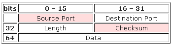
- Source port – ID of the calling port.
- Destination port – ID of the called port.
- Length — Length of UDP header and UDP data.
- Checksum — Calculated checksum of the header and data fields.
UDP has no reordering or recovery mechanism. However, UDP provides data transfer and multiplexing using port numbers as TCP but, UDP uses lesser bytes of overhead and processing than TCP. Hence, applications using UDP should be tolerant of the lost data. VoIP uses UDP as time to discover and re-transmit lost voice packet adds too much delay. Similarly any DNS request failure will be retried.
