The purpose of scales is to allow an engineer, architect, technician or contractor to determine scaled measurements from drawings or maps very quickly and easily. Drawings and maps are drawn to different scales such as
1”= 100’, 1”=1’-0”or 1:2 (half size)
The scale ratio of a model represents the proportional ratio of a linear dimension of the model to the same feature of the original. Examples include a 3-dimensional scale model of a building or the scale drawings of the elevations or plans of a building. In such cases the scale is dimensionless and exact throughout the model or drawing.
The scale can be expressed in four ways: in words (a lexical scale), as a ratio, as a fraction and as a graphical (bar) scale. Thus on an architect’s drawing one might read
‘one centimetre to one metre’ or 1:100 or 1/100
and a bar scale would also normally appear on the drawing.
General Representation
In general a representation may involve more than one scale at the same time. For example, a drawing showing a new road in elevation might use different horizontal and vertical scales. An elevation of a bridge might be annotated with arrows with a length proportional to a force loading, as in 1 cm to 1000 newtons: this is an example of a dimensional scale. A weather map at some scale may be annotated with wind arrows at a dimensional scale of 1 cm to 20 mph.
Map scales require careful discussion. A town plan may be constructed as an exact scale drawing, but for larger areas a map projection is necessary and no projection can represent the Earth’s surface at a uniform scale. In general the scale of a projection depends on position and direction. The variation of scale may be considerable in small scale maps which may cover the globe. In large scale maps of small areas the variation of scale may be insignificant for most purposes but it is always present. The scale of a map projection must be interpreted as a nominal scale. (The usage large and small in relation to map scales relates to their expressions as fractions. The fraction 1/10,000 used for a local map is much larger than 1/100,000,000 used for a global map. There is no fixed dividing line between small and large scales.)
Types of scale
Civil engineering scale
Full Divided Scale
1”is divided into equal decimal units of10, 20, 30, 40, 50, 60 and 80 divisions. For example, 1”= 100’is a typical scale used for Civil Engineering Drawings. This means that 1”on the drawing represents 100’in the real world.
Civil Engineers typically design large things such as, bridges, roads, buildings, shopping centers etc. Therefore typical scales used include:1”= 100’for plan views of highway designs and 1”= 5’vertical and 1”=100’horizontal for profile views. Section views are typically 1”= 5’vertical and 1”= 10’horizontal.
Architect’s scale
Architects are involved in large scale projects as well as smaller scale projects. They use a wide range of different scales for their drawings. Many Structural Engineering detail drawings are read using the Architect’s scale. Achitect’s scale always reads X”= 1’-0”For example, ½”= 1’-0”or 3”= 1’-0”.
Common metric scales
- 1:1Full Size
- 1: 2Half Size
- 1:51/5Size
- 1:20 1/20 Size (canbe used for 1/200size)
- 1:331/3LPSize
- 1:50 (can be used for 1/5size)
- 1: 100 (can be usedfor full size)
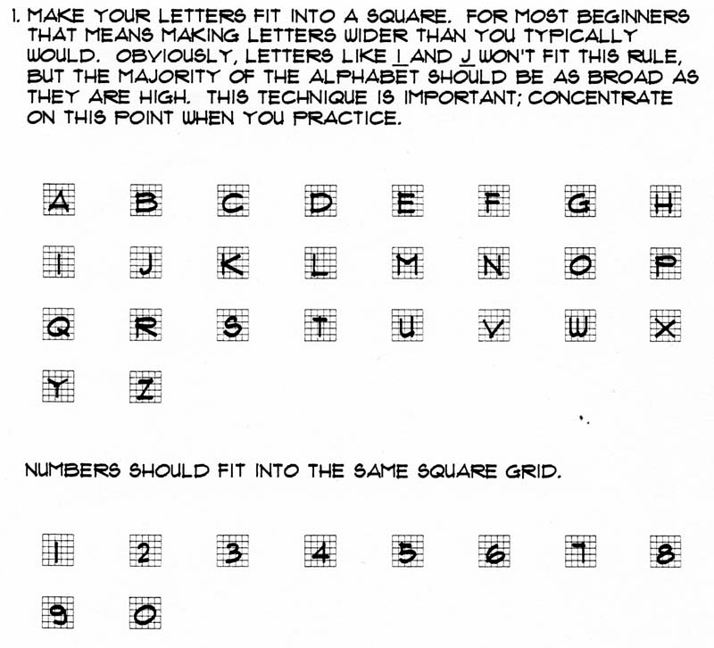
Lettering
Rules of lettering
- Use guide lines for all lettering.
- Maintain a uniform point on your lead.
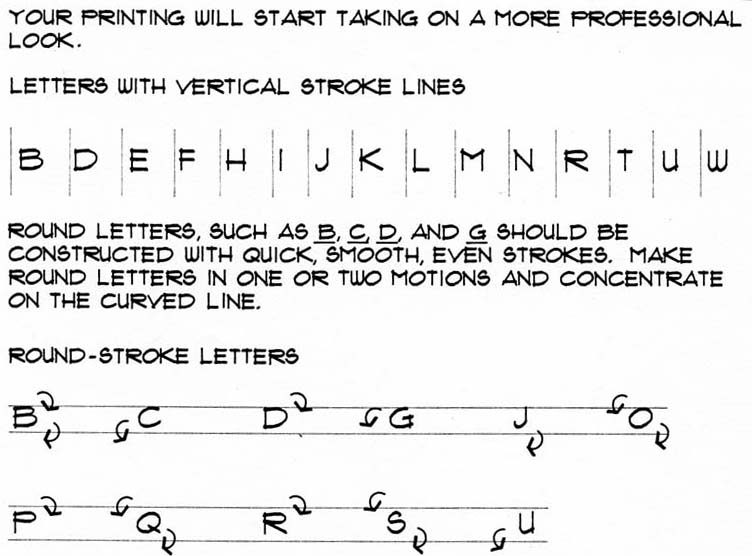
- Make vertical line strokes first.
- Place a piece of paper under your hand to protect your drawing.
- Clean the graphite off your drawing by using your brush, not your hand.
- Be critical about your lettering.
- Practice your lettering often.
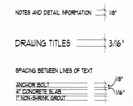
- All notes on drawings should be 1/8” high.
- All titles on drawings should be 3/16” high.
- All lettering should be dark, crisp and sharp.
- All lettering should be neat and legible.