You can use hatching to fill an area with a selected pattern or color. You can create a wipeout object to blank out an area.
Hatch Boundaries
You can hatch an enclosed area or hatch within a specified boundary using HATCH. By default, HATCH creates associative hatches that are updated when the boundary is changed. You create a hatch by selecting an object to hatch or by defining a boundary and then specifying an internal point. A hatch boundary can be any combination of objects, such as lines, arcs, circles, and polylines, that forms an enclosed area.
Enclosed areas within the hatch area are referred to as islands. You can hatch them or leave them unhatched depending on the Islands setting in the Hatch and Gradient dialog box. If you are hatching a small area in a complex drawing, you can use boundary sets to speed the process. Objects can be hatched only if they are in a plane parallel to the XY plane of the current UCS.
Hatch Patterns and Fills
You can hatch an area using a predefined hatch pattern, define a simple line pattern using the current linetype, or create more complex hatch patterns. One type of pattern is called solid, which fills an area with a solid color.
You can also create a gradient fill, which uses a transition between shades of one color or between two colors. Gradient fills can be used to enhance presentation drawings, giving the appearance of light reflecting on an object.
Define the Boundaries of a Hatch – You can choose from several methods to specify the boundaries of a hatch.
- Specify a point in an area that is enclosed by objects.
- Select objects that enclose an area.
- Drag a hatch pattern into an enclosed area from a tool palette or DesignCenter.
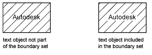
When you hatch a drawing, whole or partial objects that are not part of the object boundary are ignored. If a hatch line encounters an object such as text, an attribute, or a solid-fill object, and if the object is selected as part of the boundary set, HATCH hatches around the object.
If you want to hatch an area whose boundary is not quite closed, you can set the HPGAPTOL system variable to bridge gaps and treat the boundary as closed. HPGAPTOL applies only to gaps between lines and arcs that, if extended, would meet. To reduce file size, a hatched area is defined in the drawing database as a single graphical object.
Add Hatch Patterns and Solid Fills – You can use several methods to add hatch patterns to your drawing.
- The HATCH command provides the most options.
- You can drag hatches from a tool palette. Use tool palettes when you need additional speed and convenience. With the Tool Palettes window open, you can right-click a pattern tool to access the Tool Properties dialog box from the shortcut menu. This dialog box contains several hatch pattern options that are also available through HATCH. For example, you can specify the scale and spacing for the hatch pattern.
- You can also use DesignCenter.
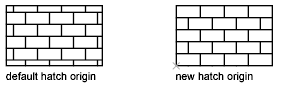
Control the Hatch Origin – By default, hatch patterns always “line up” with each other. However, sometimes you might need to move the starting point, called the origin point, of the hatch. For example, if you create a brick pattern, you might want to start with a complete brick in the lower-left corner of the hatched area. In that case, use the Hatch Origin options in the Hatch and Gradient dialog box.
The location and behavior of a hatch pattern depends on the HPORIGIN, HPORIGINMODE, and HPINHERIT system variables, and the location and orientation of the user coordinate system.
Choose a Hatch Pattern – The program supplies a solid fill and more than 50 industry-standard hatch patterns that you can use to differentiate the components of objects or represent object materials. The program also comes with 14 hatch patterns that conform to the ISO (International Standards Organization) standards. When you select an ISO pattern, you can specify a pen width, which determines the lineweight in the pattern.
On the Hatch of the Hatch and Gradient dialog box, the Type and Pattern area displays the names of all the hatch patterns defined in the acad.pat text file. You can add new hatch patterns to the dialog box by adding their definitions to the acad.pat file.
Create Associative Hatches – An associative hatch is updated when you change the boundary. Hatched areas created with HATCH are associative by default. This setting is stored in the system variable HPASSOC. Hatches created by dragging hatch patterns from tool palettes or DesignCenter™ use the setting in HPASSOC. You can remove hatch associativity at any time or use HATCH to create a nonassociative hatch. When the HPGAPTOL system variable is set to 0 (the default), associativity is automatically removed if editing creates an open boundary.
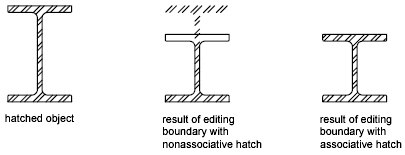
You can use HATCH to create nonassociative hatches, which are independent of their boundaries.
Create an Annotative Hatch – An annotative hatch is defined at a paper size. You can create individual annotative hatch objects as well as annotative hatch patterns. Use an annotative hatch to symbolically represent material such as sand, concrete, steel, earth, etc.
Assign a Draw Order to a Hatch – You can assign a draw order to a hatch so that it is drawn either behind or in front of the hatch boundary, or behind or in front of all other objects. When you create a hatch, by default the hatch is drawn behind the hatch boundary. This makes it easier to view and select the hatch boundary. You can change the draw order of the hatch so that the hatch is drawn in front of the hatch boundary instead, or either behind or in front of all other objects. This setting is stored in the HPDRAWORDER system variable. Hatches created by dragging hatch patterns from tool palettes or DesignCenter use the draw order setting in HPDRAWORDER.
Limit Hatch Pattern Density – If you create a very dense hatch, the program may reject the hatch and display a message indicating that the hatch scale is too small or its dash length too short. You can change the maximum number of hatch lines by setting the HPMAXLINES system variable. You can set values between 100 and 10000000 (ten million). The default value for HPMAXLINES is 1000000.
Edit Hatch Boundaries – Because there are so many combinations of objects that can be hatched, editing hatched geometry can produce unexpected results. If you create a hatch that you don’t want, you can undo it, trim the hatch, or delete the hatch and rehatch the area.
Create Custom Hatch Patterns – You can also define your own hatch pattern using the current linetype with the User Defined Pattern option of the Hatch and Gradient dialog box, or you can create more complex hatch patterns.
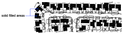
Create Solid-Filled Areas
There are several methods for creating solid-filled areas. Solid-filled areas can be created using
- Hatches with a solid hatch pattern ( HATCH)
- 2D solids ( SOLID)
- Wide polylines or donuts ( PLINE, DONUT)
Use Predefined Hatch Patterns
You can choose from more than 50 industry-standard hatch patterns. Additional hatch patterns are available from external pattern libraries. The program supplies a solid fill and more than 50 industry-standard hatch patterns, which can represent materials such as earth, brick, or clay.
Fourteen hatch patterns conform to International Standards Organization (ISO) standards. When you select an ISO pattern, you can specify a pen width, which determines the lineweight in the pattern. In addition to using the patterns supplied with the program, you can use patterns from an external pattern library. These patterns are listed by name and are displayed in the Hatch Pattern Palette dialog box.
Create a Blank Area to Cover Objects
Wipeout objects cover existing objects with a blank area to make room for notes or to mask details. A wipeout object is a polygonal area that masks underlying objects with the current background color. This area is bounded by the wipeout frame, which you can turn on for editing and turn off for plotting.
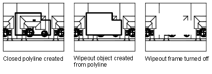
You can create a wipeout object by specifying a polygonal area with a series of points, or you can convert a closed polyline into a wipeout object. You can move or delete a wipeout object by first turning on wipeout frames so you can select it.
