Interface Options
Set Up the Drawing Area – You can adjust the color and display schemes used in the application and drawing windows, and control the behavior of general features such as zoom transitions. Many of the settings are available from shortcut menus and the Options dialog box. Some workspace elements, such as the presence and location of toolbars and palettes, can be specified and saved using the Customize User Interface dialog box. Some settings affect how you work in the drawing area
- Background Colors (Options dialog box, Display tab). You specify the background colors used in the layout and Model tabs and the color used for prompts and crosshairs.
- Color Scheme (Options dialog box, Display tab, Colors). You specify a dark or light color scheme for the overall user interface. The settings affect the window frame background, status bar, title bar, menu browser frame, toolbars, and palettes.
- Background Colors (Options dialog box, Display tab, Colors). You specify the background colors used in model space, layouts, and the block editor. Background colors on the Model tab change to indicate whether you are working in a 2D design context, 3D modeling (parallel projection), or 3D modeling (perspective projection).
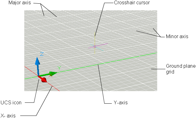
- UCS Icon and Crosshairs Cursor (Options dialog box, 3D Modeling tab). You specify that the 3D display options and labels for the UCS icon can be set in the 3D Modeling tab of the Options dialog box.
- Color Assignments for X, Y, and Z (Options dialog box, Display tab, Colors). In 3D views, any interface elements that are associated with the UCS X, Y, and Z axis use special color assignments. The X axis is colored or tinted red, the Y axis is green, and the Z axis is blue. These tints can be turned on or off in the Drawing Window Colors dialog box.
- Clean Screen. You can expand the drawing display area to display only the menu bar, status bar, and command window with the clean screen button on the application status bar. Click the button again to restore the previous setup.
- View Transitions. You can control whether view transitions are smooth or instantaneous when you pan, zoom, or change from one view to another (VTOPTIONS command). The default is a smooth transition.
3D Modeling with Perspective Projection – You can set specific display options when working with 3D models using perspective projection. Using the Options dialog box, you can specify the following options when your 3D model is set to use a perspective view:
- Ground Plane (Options dialog box, Display tab, Colors). When perspective projection is turned on, the XY plane of the UCS displays as a ground plane with a gradient color. The ground plane displays a gradient from the ground horizon to the ground origin.
- Sky (Options dialog box, Display tab, Colors). The area not covered by the ground plane is the sky, which displays a gradient color from the sky horizon to the sky zenith.
- Underground (Options dialog box, Display tab, Colors). If the ground plane is viewed from below ground, the ground plane displays a gradient from the earth horizon to the earth azimuth.
Ground Plane Grid (Options dialog box, Display tab, Colors). When perspective projection is turned on, the grid displays as a ground plane grid. Colors are set for major grid lines, minor grid lines, and axis lines.
Model Space and Layouts – You can control how you change between model space and one or more layouts. The classic interface provides a Model tab and one or more layout tabs. To optimize space in the drawing area, you can turn off these tabs and use the equivalent buttons on the status bar. The control to change between the two interface designs is included as an item on the Model and layout tab shortcut menu, and on the shortcut menu of the Model/Layout button on the status bar.
Dockable Windows – Windows such as the Properties palette, tool palettes, and DesignCenter can be docked, anchored, or floated. Settings for these and other options are often changed on a shortcut menu, available by right-clicking the title bar of the palette or window.
- Drag an edge of the window to change its size. If the window has panes, drag the bar between panes to resize the panes.
- Allow Docking. Select this option if you want to dock or anchor a dockable window. A docked window adheres to one side of the application window, causing the drawing area to be resized.
- Attach, or anchor, a dockable window or palette to the left or right side of the drawing area. An anchored window rolls open and closed as the cursor moves across it. When an anchored window is open, its content overlaps the drawing area. An anchored window cannot be set to stay open. The Allow Docking option must be selected before you can anchor a window.
- Auto-hide. A floating window rolls open and closes as the cursor moves across it. When this option is cleared, the window stays open continuously. Docked windows with auto-hide show up as a bar inside the application.
- Sets the degree of transparency for the window and on mouse over. The window becomes transparent so that it does not obscure objects under it. The window becomes more opaque when it is moused over. This option is not available for all windows.
Task-Based Workspaces – Workspaces are sets of menus, toolbars, palettes, and ribbon control panels that are grouped and organized so that you can work in a custom, task-oriented drawing environment. When you use a workspace, only the menus, toolbars, and palettes that are relevant to a task are displayed. In addition, a workspace may automatically display the ribbon, a special palette with task-specific control panels.
You can easily switch between workspaces. The following task-based workspaces are already defined in the product – 2D Drafting & Annotation, 3D Modeling and AutoCAD Classic. For example, when you create 3D models, you can use the 3D Modeling workspace that contains only 3D-related toolbars, menus, and palettes. Interface items that you do not need for 3D modeling are hidden, maximizing the screen area available for your work. When you make changes to your drawing display (such as moving, hiding, or displaying a toolbar or a tool palette group) and you want to preserve the display settings for future use, you can save the current settings to a workspace.
Profiles – Profiles store drawing environment settings. You can create profiles for different users or projects, and you can share profiles by importing and exporting them as files. Profiles store settings such as the following:
- Default search and project file paths
- Template file locations
- Initial folder specified in file navigation dialog boxes
- Default linetype and hatch pattern files
- Printer defaults
Profile information is typically set on the Files tab of the Options dialog box, stored in the system registry, and can be exported to a text file (an ARG file).
Startup – Command line switches can specify a separate startup routine for each project. You can use command line switches to specify several options when you start the program. For example, you can run a script, start with a specified drawing template, and display a specified view when a drawing is opened. With command line switches, you can also set up several program icons, each with different start-up options.
Command line switches are parameters you can add to the acad.exe command line associated with a Microsoft® Windows® shortcut icon or the Windows Run dialog box. You can include several switches within a single command line. Valid switches are listed in the following table.
| Switch | Description |
| /b | Script name. Designates a script to run after you start the program (b stands for batch process). Scripts can be used to set up drawing parameters in a new drawing file. An SCR file type is assumed. |
| /t | Template file name. Creates a new drawing based on a template or prototype drawing. A DWT file type is assumed. |
| /c | Configuration folder. Specifies the path for the hardware configuration file that you want to use. You can specify a directory or a particular file. A CFG file type is assumed. |
| /v | View name. Designates a particular view of the drawing for display at startup. |
| /s | Support folders. Designates support folders other than the current folder. Drawing support files include text fonts, menus, AutoLISP files, linetypes, and hatch patterns. The maximum number of folders you can specify in the path is 15. Each folder name is delimited by semicolons. |
| /r | Default system pointing |
| device | Restores the default system pointing device. It creates a new configuration file (acad2010.cfg) and renames the previous configuration file to acad.bak. |
| /nologo | No AutoCAD logo screen |
| /w | Default workspace. Designates which workspace in the loaded CUIx files should be restored on startup. |
