When a command prompts you for a point, you can use the pointing device to specify a point, or you can enter a coordinate value at the command prompt. When dynamic input is on, you can enter coordinate values in tooltips near the cursor. You can enter two-dimensional coordinates as either Cartesian (X,Y) or polar coordinates.
Cartesian and Polar Coordinates
A Cartesian coordinate system has three axes, X, Y, and Z. When you enter coordinate values, you indicate a point’s distance (in units) and its direction (+ or -) along the X, Y, and Z axes relative to the coordinate system origin (0,0,0).
In 2D, you specify points on the XY plane, also called the workplane. The workplane is similar to a flat sheet of grid paper. The X value of a Cartesian coordinate specifies horizontal distance, and the Y value specifies vertical distance. The origin point (0,0) indicates where the two axes intersect.
Polar coordinates use a distance and an angle to locate a point. With both Cartesian and polar coordinates, you can enter absolute coordinates based on the origin (0,0), or relative coordinates based on the last point specified.
Another method of entering a relative coordinate is by moving the cursor to specify a direction and then entering a distance directly. This method is called direct distance entry.
You can enter coordinates in scientific, decimal, engineering, architectural, or fractional notation. You can enter angles in grads, radians, surveyor’s units, or degrees, minutes, and seconds. The UNITS command controls unit format.
The current cursor location is displayed as a coordinate value on the status bar, as ![]()
There are three types of coordinate display: static, dynamic, and distance and angle.
- Static display. Updates only when you specify a point.
- Dynamic display. Updates as you move the cursor.
- Distance and angle display. Updates the relative distance (distance<angle) as you move the cursor. This option is available only when you draw lines or other objects that prompt for more than one point.
2D Coordinates
Absolute and relative 2D Cartesian and polar coordinates determine precise locations of objects in a drawing.
Cartesian Coordinates – You can use absolute or relative Cartesian (rectangular) coordinates to locate points when creating objects. To use Cartesian coordinates to specify a point, enter an X value and a Y value separated by a comma (X,Y). The X value is the positive or negative distance, in units, along the horizontal axis. The Y value is the positive or negative distance, in units, along the vertical axis.
Absolute coordinates are based on the UCS origin (0,0), which is the intersection of the X and Y axes. Use absolute coordinates when you know the precise X and Y values of the point. With dynamic input, you can specify absolute coordinates with the # prefix. If you enter coordinates on the command line instead of in the tooltip, the # prefix is not used. For example, entering #3,4 specifies a point 3 units along the X axis and 4 units along the Y axis from the UCS origin.
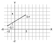
The following example draws a line beginning at an X value of -2, a Y value of 1, and an endpoint at 3,4. Enter the following in the tooltip:
Command: line
From point: #-2,1
To point: #3,4
The line is located as
Relative coordinates are based on the last point entered. Use relative coordinates when you know the location of a point in relation to the previous point. To specify relative coordinates, precede the coordinate values with an @ sign. For example, entering @3,4 specifies a point 3 units along the X axis and 4 units along the Y axis from the last point specified.
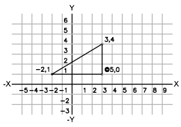
The following example draws the sides of a triangle. The first side is a line starting at the absolute coordinates -2,1 and ending at a point 5 units in the X direction and 0 units in the Y direction. The second side is a line starting at the endpoint of the first line and ending at a point 0 units in the X direction and 3 units in the Y direction. The final line segment uses relative coordinates to return to the starting point.
Command: line
From point: #-2,1
To point: @5,0
To point: @0,3
To point: @-5,-3
To enter absolute Cartesian coordinates (2D)
- At a prompt for a point, enter coordinates in the tooltip using the following format: #x,y
- If dynamic input is turned off, enter coordinates on the command line using the following format: x,y
To enter relative Cartesian coordinates (2D)
- At a prompt for a point, enter coordinates using the following format: @x,y
3D Coordinates
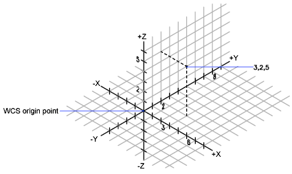
3D Cartesian coordinates specify a precise location by using three coordinate values: X, Y, and Z. Entering 3D Cartesian coordinate values (X,Y,Z) is similar to entering 2D coordinate values (X,Y). In addition to specifying X and Y values, you also specify a Z value using the following format:
X,Y,Z – For the following examples, it is assumed that dynamic input is turned off or that the coordinates are entered on the command line. With dynamic input, you specify absolute coordinates with the # prefix. In the illustration below, the coordinate values of 3,2,5 indicates a point 3 units along the positive X axis, 2 units along the positive Y axis, and 5 units along the positive Z axis.
Use Default Z Values – When you enter coordinates in the format X,Y, the Z value is copied from the last point you entered. As a result, you can enter one location in the X,Y,Z format and then enter subsequent locations using the X,Y format with the Z value remaining constant. For example, if you enter the following coordinates for a line
From point: 0,0,5
To point: 3,4
both endpoints of the line will have a Z value of 5. When you begin or open any drawing, the initial default value of Z is greater than 0.
Absolute and Relative Coordinates – As with 2D coordinates, you can enter absolute coordinate values, which are based on the origin, or you can enter relative coordinate values, which are based on the last point entered. To enter relative coordinates, use the @ sign as a prefix. For example, use @1,0,0 to enter a point one unit in the positive X direction from the previous point. To enter absolute coordinates at the command prompt, no prefix is necessary.
Digitize Coordinates – When you enter coordinates by digitizing, the UCS Z value for all coordinates is 0. You can use ELEV to set a default height above or below the Z = 0 plane for digitizing without moving the UCS.
To enter absolute coordinates (3D)
- At a prompt for a point, enter coordinates in the tooltip using the following format: #x,y,z
- If dynamic input is turned off, enter coordinates on the command line using the following format: x,y,z
To enter relative coordinates (3D)
- At a prompt for a point, enter coordinates using the following format: @x,y,z
Cylindrical Coordinates
3D cylindrical coordinates describe a precise location by a distance from the UCS origin in the XY plane, an angle from the X axis in the XY plane, and a Z value.
Cylindrical coordinate entry is the 3D equivalent of 2D polar coordinate entry. It specifies an additional coordinate on an axis that is perpendicular to the XY plane. Cylindrical coordinates define points by a distance in the XY plane from the UCS origin, an angle from the X axis in the XY plane, and a Z value. You specify a point using absolute cylindrical coordinates with the following syntax:
X<[angle from X axis],Z
For the following examples, it is assumed that dynamic input is turned off or that the coordinates are entered on the command line. With dynamic input, you specify absolute coordinates with the # prefix. In the illustration below, 5<30,6 indicates a point 5 units from the origin of the current UCS, 30 degrees from the X axis in the XY plane, and 6 units along the Z axis.
When you need to define a point based on a previous point rather than the UCS origin, you can enter relative cylindrical coordinate values with the @ prefix. For example, @4<45,5 specifies a point 4 units in the XY plane from the last point entered, at an angle of 45 degrees from the positive X direction, and extending 5 units in the positive Z direction.
To enter relative cylindrical coordinates
At a prompt for a point, enter the coordinate values using the following format: @x<angle from the X axis,z For example, @4<60,2 represents a location that is 4 units along the X axis from the last point measured at 60 degrees from the positive X axis and at 2 units in the positive Z direction.
Spherical Coordinates
3D spherical coordinates specify a location by a distance from the origin of the current UCS, an angle from the X axis in the XY plane, and an angle from the XY plane.
Spherical coordinate entry in 3D is similar to polar coordinate entry in 2D. You locate a point by specifying its distance from the origin of the current UCS, its angle from the X axis (in the XY plane), and its angle from the XY plane, each angle preceded by an open angle bracket (<) as in the following format:
X<[angle from X axis]<[angle from XY plane]
For the following examples, it is assumed that dynamic input is turned off or that the coordinates are entered on the command line. With dynamic input, you specify absolute coordinates with the # prefix.
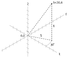
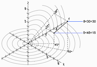
In the following illustration, 8<60<30 indicates a point 8 units from the origin of the current UCS in the XY plane, 60 degrees from the X axis in the XY plane, and 30 degrees up the Z axis from the XY plane. 5<45<15 indicates a point 5 units from the origin, 45 degrees from the X axis in the XY plane, and 15 degrees up from the XY plane.
When you need to define a point based on a previous point, enter the relative spherical coordinate values by preceding them with the @ sign.
To enter relative spherical coordinates
- At a prompt for a point, enter the coordinate values using the following format: @x<angle from the x axis<angle from the xy plane For example, @4<60<30 represents a location that is 4 units from the last point measured at 60 degrees from the positive X axis in the XY plane and at 30 degrees from the XY plane.
UCS and WCS
There are two coordinate systems: a fixed system called the world coordinate system (WCS) and a movable system called the user coordinate system (UCS). By default, these two systems are coincident in a new drawing.
Normally in 2D views, the WCS X axis is horizontal and the Y axis is vertical. The WCS origin is where the X and Y axes intersect (0,0). All objects in a drawing file are defined by their WCS coordinates. However, it is usually more convenient to create and edit objects based on the movable UCS.
User Coordinate System
Virtually all coordinate entry as well as many other tools and operations reference the current UCS. 2D tools and operations that depend on the location and orientation of the UCS include the following:
- Absolute and relative coordinate entry
- Absolute reference angles
- Definition of horizontal and vertical for Ortho mode, polar tracking, object snap tracking, grid display, and grid snap
- Orientation of horizontal and vertical dimensions
- Orientation of text objects
- View rotation using the PLAN command
Moving or rotating the UCS can make it easier to work on particular areas of a drawing.
You can relocate the user coordinate system with methods such as the following:
- Move the UCS by defining a new origin point.
- Align the UCS with an existing object.
- Rotate the UCS by specifying a new origin point and a point on the new X axis.
- Rotate the current UCS a specified angle around the Z axis.
- Revert to the previous UCS.
- Restore the UCS to be coincident with the WCS.
Each of these methods have a corresponding option in the UCS command. Once you have defined a UCS, you can name it and then restore it when you need to use it again.
The User Coordinate System defines
- The XY plane, also called the work plane, on which objects are created and modified
- The horizontal and vertical directions used for features like Ortho mode, polar tracking, and object snap tracking
- The alignment and angle of the grid, hatch patterns, text, and dimension objects
- The origin and orientation for coordinate entry and absolute reference angles
- For 3D operations, the orientation of work planes, projection planes, and the Z axis for vertical direction and axis of rotation
You can change the location and orientation of the current UCS by clicking the UCS icon and using its grips, or with the UCS command. Display options for the UCS icon are available with the UCSICON command.
UCS in 3D
When you work in 3D, the user coordinate system is useful for entering coordinates, creating 3D objects on 2D workplanes, and rotating objects in 3D. When you create or modify objects in a 3D environment, you can move and reorient the UCS in 3D model space to simplify your work. The XY plane of the UCS is called the workplane. Important operations on objects in a 3D environment that depend on the location and orientation of the UCS include the following
- Establish the workplane in on which to create and modify objects
- Establish the workplane that contains the grid display and grid snap
- Establish a new UCS Z axis about which to rotate objects in 3D
- Determine up and down directions as well as horizontal and vertical for Ortho mode, polar tracking, and object snap tracking
- Define a 3D view directly into the workplane with the PLAN command
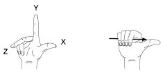
When you create or modify objects in a 3D environment, you can move and reorient the UCS anywhere in 3D space to simplify your work. The UCS is useful for entering coordinates, creating 3D objects on 2D work planes, and rotating objects in 3D. The UCS icon follows the traditional right-hand rule in determining positive axis directions and rotation directions.
UCS in Paper Space – You can move and rotate the UCS in paper space on a layout; however, the UCS in paper space is restricted to 2D operations.
The World Coordinate System (WCS) – All objects in a drawing are defined by their coordinates in the World Coordinate System (WCS), which cannot be moved or rotated. The WCS and the UCS are initially coincident in new drawings.
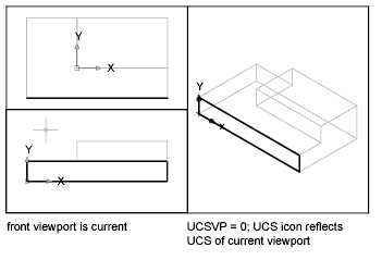
Assigning UCS Definitions to Viewports – To facilitate editing objects in different views, you can define a different user coordinate system (UCS) for each view. Each time you make a viewport current, you can use the same UCS orientation that you used the last time that viewport was current.
The UCS in each viewport is controlled by the UCSVP system variable, which can also be accessed with the UCSMAN command, on the Settings tab. When UCSVP is set to 1 in a viewport, the UCS last used in that viewport is saved with the viewport and is restored when the viewport is made current again. When UCSVP is set to 0 in a viewport, its UCS is always the same as the UCS in the current viewport.
For example, you might set up three viewports: a top view, front view, and isometric view. If you set the UCSVP system variable to 0 in the isometric viewport, you can use the Top UCS in both the top viewport and the isometric viewport. When you make the top viewport current, the isometric viewport’s UCS reflects the UCS top viewport. Likewise, making the front viewport current switches the isometric viewport’s UCS to match that of the front viewport.
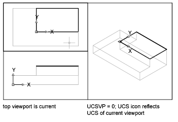
The example is illustrated in the following illustrations. The one shows the isometric viewport reflecting the UCS of the upper-left, or top, viewport, which is current.

The next illustration shows the change that occurs when the lower-left, or front, viewport is made current. The UCS in the isometric viewport is updated to reflect the UCS of the front viewport.
To enter coordinates relative to the WCS – Entering @*2,0,0 specifies a point two units in the X direction of the last point entered relative to the WCS. Entering @2,0,0 specifies a point two units in the X direction of the last point entered relative to the UCS. In practice, most coordinates are entered relative to the UCS rather than the WCS.
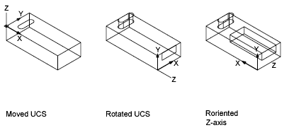
Several methods are available for manipulating the user coordinate system in 3D. You can also save and restore user coordinate system orientations. You define a user coordinate system (UCS) to change the location of the 0,0,0 origin point, the location and rotation of the XY plane, and the orientation of the XY plane or Z axis. You can locate and orient a UCS anywhere in 3D space, and you can define, save, and recall as many saved UCS locations as you require.
If multiple viewports are active, you can assign a different UCS to each viewport. With the UCSVP system variable turned on, you can lock a UCS to a viewport, automatically restoring the UCS each time that viewport is made current.
Define the UCS Location – You can define a UCS in the following ways:
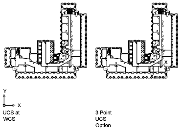
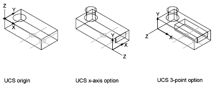
- Specify a new origin (one point), new X axis (two points), or new XY plane (three points).
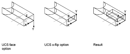
- Align the UCS by selecting a face on a 3D solid object. The selection can be on a face or on an edge of the solid.
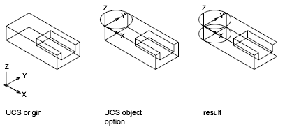
- Align the new UCS with an existing object. The origin of the UCS is located at the vertex nearest to where the object was selected.
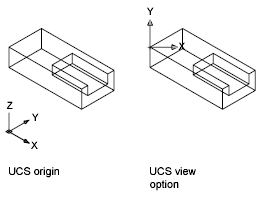
- Align the new UCS with the current viewing direction.
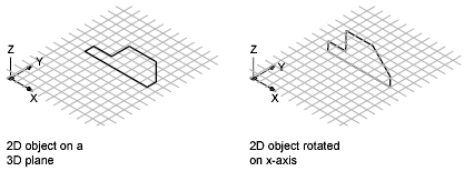
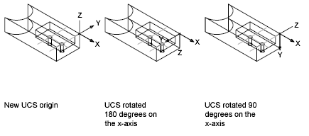
- Rotate the current UCS around any of its three major axes.
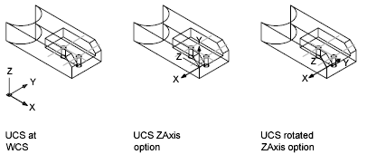
- Reorient the XY plane by specifying a new Z axis.
Use UCS Presets – If you do not want to define your own UCS, you can choose from several preset coordinate systems. The images on the Orthographic UCSs tab of the (Named) UCS dialog box show the available choices.
Change the Default Elevation – The ELEV command sets the default Z value for new objects above or below the XY plane of the current UCS. This value is stored in the ELEVATION system variable.
NoteGenerally, it is recommended that you leave the elevation set to zero and control the XY plane of the current UCS with the UCS command.
Change the UCS in Paper Space – You can define a new UCS in paper space just as you can in model space; however, the UCS in paper space is restricted to 2D manipulation. Although you can enter 3D coordinates in paper space, you cannot use 3D viewing commands such as PLAN and VPOINT.
User Coordinate System Orientations to Viewports
To facilitate editing objects in different views, you can define a different user coordinate system orientation for each view. Multiple viewports provide different views of your model. For example, you might set up viewports that display top, front, right side, and isometric views. To facilitate editing objects in different views, you can define a different UCS for each view. Each time you make a viewport current, you can begin drawing using the same UCS you used the last time that viewport was current.
The UCS in each viewport is controlled by the UCSVP system variable. When UCSVP is set to 1 in a viewport, the UCS last used in that viewport is saved with the viewport and is restored when the viewport is made current again. When UCSVP is set to 0 in a viewport, its UCS is always the same as the UCS in the current viewport.
For example, you might set up three viewports: a top view, front view, and isometric view. If you set the UCSVP system variable to 0 in the isometric viewport, you can use the Top UCS in both the top viewport and the isometric viewport. When you make the top viewport current, the isometric viewport’s UCS reflects the UCS top viewport. Likewise, making the front viewport current switches the isometric viewport’s UCS to match that of the front viewport.
The example is illustrated in the following figures. The first figure shows the isometric viewport reflecting the UCS of the upper-left, or top, viewport, which is current.

The second figure shows the change that occurs when the lower-left, or front, viewport is made current. The UCS in the isometric viewport is updated to reflect the UCS of the front viewport.
In previous releases, the UCS was a global setting for all viewports in either model or paper space. If you want to restore the behavior of previous releases, you can set the value of the UCSVP system variable to 0 in all active viewports.
Display of the User Coordinate System Icon
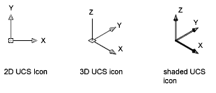
To help visualize the current orientation of the user coordinate system, you can display the user coordinate system icon. Several versions of this icon are available, and you can change its size, location, and color. To indicate the location and orientation of the UCS, the UCS icon is displayed either at the UCS origin point or in the lower-left corner of the current viewport. You can choose one of three styles of icon to represent the UCS.
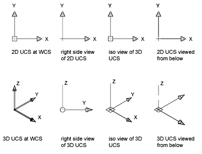
Use the UCSICON command to choose between displaying the 2D or the 3D UCS icon. The shaded UCS icon is displayed for a shaded 3D view. To indicate the origin and orientation of the UCS, you can display the UCS icon at the UCS origin point using the UCSICON command. If the icon is displayed at the origin of the current UCS, a cross (+) appears in the icon. If the icon is displayed in the lower-left corner of the viewport, no cross appears in the icon. If you have multiple viewports, each viewport displays its own UCS icon. The UCS icon is displayed in various ways to help you visualize the orientation of the workplane. The following figure shows some of the possible icon displays.
You can use the UCSICON command to switch between the 2D UCS icon and the 3D UCS icon. You can also use the command to change the size, color, arrowhead type, and icon line width of the 3D UCS icon.
The UCS broken pencil icon replaces the 2D UCS icon when the viewing direction is in a plane parallel to the UCS XY plane. The broken pencil icon indicates that the edge of the XY plane is almost perpendicular to your viewing direction. This icon warns you not to use your pointing device to specify coordinates. When you use the pointing device to locate a point, it’s normally placed on the XY plane. If the UCS is rotated so that the Z axis lies in a plane parallel to the viewing plane—that is, if the XY plane is edge-on to the viewer—it may be difficult to visualize where the point will be located. In this case, the point will be located on a plane parallel to your viewing plane that also contains the UCS origin point. For example, if the viewing direction is along the X axis, coordinates specified with a pointing device will be located on the YZ plane, which contains the UCS origin point. Use the 3D UCS icon to help you visualize which plane these coordinates will be projected on; the 3D UCS icon does not use a broken pencil icon.
