It is an interesting design for a concentrating collector makes use of the fact that when the rim of a parabola is tilted toward the sun, the rays are no longer concentrated to a point, but are all reflected somewhere below the focus. The rays striking the half of the parabola which is now tilted away from the sun are reflected somewhere above the focus. This can be seen on Figure 1, where the rays on the right-hand side are reflecting below the focus and the rays on the left-hand side are reflecting above the focus. If the half parabola tilted away from the sun is discarded, and replaced with a similarly shaped parabola with its rim pointed toward the sun, we have a concentrator that reflects (i.e. traps) all incoming rays to a region below the focal point.
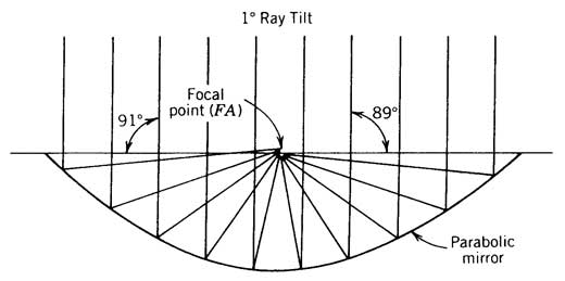
Figure 1 Off-axis light reflection from parabolic mirror.
Since the rays are no longer concentrated to a single point, this design is called a non-imaging concentrator. A receiver is now placed in the region below the focus and we have a concentrator that will ´trap´ sun rays coming from any angle between the focal line of the two parabola segments. Receivers can be flat plates at the base of the intersection of the two parabola, or a cylindrical tube passing through the region below the focus.
The basic shape of the compound parabolic concentrator (CPC) is illustrated in Figure 2. The name, compound parabolic concentrator, derives from the fact that the CPC is comprised of two parabolic mirror segments with different focal points as indicated. The focal point for parabola A (FA) lies on parabola B, whereas the focal point of parabola B (FB) lies on parabola A. The two parabolic surfaces are symmetrical with respect to reflection through the axis of the CPC.
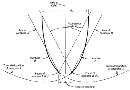
Figure 2 The compound parabolic concentrator (CPC).
The axis of parabola A is also shown in Figure 2 and, by definition, passes through the focal point of parabola A and the axis of parabola B likewise passes through the focal point of parabola B. The angle that the axes of the parabola A and B make with axis of the CPC defines the acceptance angle of the CPC. Light with an incidence angle less than one-half the acceptance angle will be reflected through the receiver opening (see Figure 3a). Light with an incidence angle greater than one-half the acceptance angle will not be reflected to the receiver opening (Figure 3b) and will, in fact, eventually be reflected back out through the aperture of the CPC.
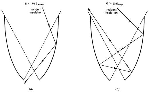
Figure 3 Light reflection from the CPC. a) Incidence angle less than acceptance angle; b) Incidence angle greater than acceptance angle.
The concentrating ability of the CPC can be understood through the use of ray tracing diagrams. If beam solar irradiance parallel to the axis of parabola A were incident on the CPC shown in Figure 2 the light would be perfectly focused (ignoring the 0.5 degree solar degree-width and any mirror inaccuracies) to point FA, the focal point of parabola A. The behavior of beam solar irradiance not parallel to the axis of parabola A is shown in Figure 1. Note that all of the solar irradiance incident on the right half of the parabola is reflected such that it passes beneath the focal point between the focal point and the surface of the parabolic mirror.
If the right half of the parabola in Figure 1 is tilted up to angle one-half the acceptance angle in order to approximate the orientation of parabola A in Figure 2, the situation would be analogous to that depicted in Figure 3a. All incident beam solar irradiance that is inclined to the right of the axis of the parabola in Figure 2 would he reflected by the right hand segment of the parabola beneath the focal point. Thus such solar irradiance would enter the receiver opening of an equivalent CPC.
The converse situation is true where the angle of incidence is greater than one-half the acceptance angle. This situation is represented by the left half of the parabola in Figure 2. In this situation, all the incident beam solar irradiance is reflected above the focal point of the parabola and would not, as indicated in Figure 3b, enter the receiver opening of an equivalent CPC.
In operation, the CPC is usually deployed with its linear receiver aligned along an E/W line. The aperture of the CPC is typically tilted toward the south so that the incident solar irradiance enters within the acceptance angle of the CPC. Provided the sun’s apparent motion does not result in the incident solar irradiance falling outside the CPC’s acceptance angle, the CPC’s aperture need not be tracked. Typically, a CPC’s aperture need not be tracked on an hourly basis throughout a day since the sun’s declination does not change more than the acceptance angle throughout a day. However, the tilt of the CPC may have to be adjusted periodically throughout the year if the incident solar irradiance moves outside the acceptance angle of the CPC.
The geometric concentration ratio of a CPC is related to the acceptance angle by
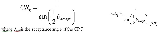
where θaccept is the acceptance angle of the CPC.
As the concentration ratio of the CPC is increased in an attempt to increase performance at elevated temperatures, the acceptance angle of the CPC must be reduced. The narrowing of the acceptance angle results in a requirement for increasing the number of tilt adjustments of the CPC throughout the year. Table lists the number of tilt adjustments needed for CPC collectors with various concentration ratios. Cosine effect changes due to these adjustments are not included on this table.
Table 10.1. Tilt Requirements of CPCs with Different Acceptance Angles (Rabl, 1980)
| Acceptance Half –Angle | Collection Time Average over Year (h/day) | Number of Adjustments per Year | Shortest Period Without Adjustment (days) | Average Collection Time if Tilt Adjusted Every Day (h/day) |
| 19.5º | 9.22 | 2 | 180 | 10.72 |
| 14º | 8.76 | 4 | 35 | 10.04 |
| 11º | 8.60 | 6 | 35 | 9.52 |
| 9º | 8.38 | 10 | 24 | 9.08 |
| 8º | 8.22 | 14 | 16 | 8.82 |
| 7º | 8.04 | 20 | 13 | 8.54 |
| 6.5º | 7.96 | 26 | 9 | 8.36 |
| 6º | 7.78 | 80 | 1 | 8.18 |
| 5.5º | 7.60 | 84 | 1 | 8.00 |
Prototype Performance – The performance of the Concentrating Parabolic Concentrator (CPC) varies with the acceptance angle. An acceptance angle of 180 degrees is equivalent to a flat-plate collector, and an acceptance angle of 0 degrees is equivalent to a parabolic concentrator.
There has not been extensive performance testing of the CPC concept. As a result, there is to the authors’ knowledge no published ΔT/I curve for CPCs. However, the Solar Energy Research Institute (Anonymous, 1979) has used the equation
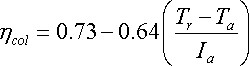
where the variables are defined as in Chapter 5. This equation is for a CPC with a concentration ratio of 5, resulting in an acceptance angle of about 19 degrees. Sharp (1979) has evaluated this equation and found it to be equivalent to that of a good parabolic trough. However, Sharp has pointed out that parasitic losses associated with pumping the heat-transfer fluid through the small tubing typically used in CPC receivers could be a major problem. Unfortunately, there is, as stated previously, a general lack of published test data.
It might be pointed out that computation of the CPC thermal energy production with the use of equation is straightforward if one assumes that the CPC tracks the sun about one axis. This is essentially what results from the multiple tilt adjustments given in table. Since there is a general lack of data on the angular dependence of diffuse solar irradiance about the beam solar irradiance, Sharp (1979) suggests use of the beam solar irradiance in computing CPC performance in clear climates even though a fraction of the diffuse solar irradiance is captured. If data were available, the diffuse solar irradiance falling within the CPC’s acceptance could be included in equation.
