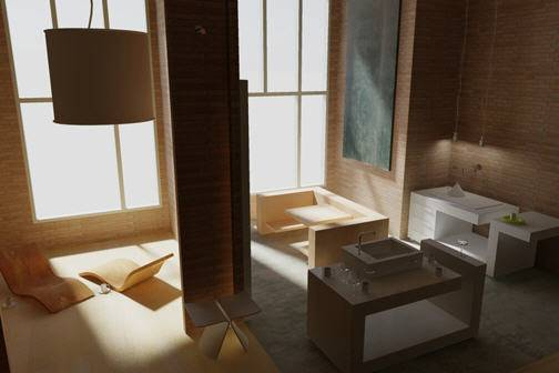
Lighting adds the finishing touch to the scene.
Default Lighting
When there are no lights in a scene, the scene is shaded with default lighting. Default lighting is derived from two distant sources that follow the viewpoint as you move around the model. All faces in the model are illuminated so that they are visually discernible. You can control brightness and contrast, but you do not need to create or place lights yourself.
When you insert custom lights or add sunlight, you can disable the default lighting. You can apply default lighting to the viewport only; at the same time, you can apply custom lights to the rendering.
Standard Lighting Workflow
You add lights to give the scene a realistic appearance. Lighting enhances the clarity and three-dimensionality of a scene. You can create point lights, spotlights, and distant lights to achieve the effects you want. You can move or rotate them with grip tools, turn them on and off, and change properties such as color and attenuation. The effects of changes are visible in the viewport in real time.
Spotlights and point lights are each represented by a different light glyph (a symbol in the drawing showing the location of the light). Distant lights and the sun are not represented by glyphs in the drawing because they do not have a discrete position and affect the entire scene. You can turn the display of light glyphs on or off while you work. By default, light glyphs are not plotted.
Photometric Lighting Workflow
For more precise control over lighting, you can use photometric lights to illuminate your model. Photometric lights use photometric (light energy) values that enable you to define lights more accurately as they would be in the real world. You can create lights with various distribution and color characteristics, or import specific photometric files available from lighting manufacturers.
Photometric lights can use manufacturers’ IES standard file format. By using manufacturers’ lighting data, you can visualize commercially available lighting in your model. Then you can experiment with different fixtures, and by varying the light intensity and color temperature, you can design a lighting system that produces the results you want.
Sun and Sky
The sun is a special light similar to a distant light. The angle of the sun is defined by the geographic location that you specify for the model and by the date and time of day that you specify. You can change the intensity of the sun and the color of its light. The sun and sky are the primary sources of natural illumination. With the sun and sky simulation, you can adjust their properties.
In the photometric workflow, the sun follows a more physically accurate lighting model in both the viewport and the rendered output. In the photometric workflow, you can also enable sky illumination (through the sky background feature), which adds soft, subtle lighting effects caused by the lighting interactions between the sun and the atmosphere.
Luminaire Objects
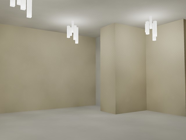
Light fixtures can be represented by embedding photometric lights in blocks that also contain geometry. A luminary assembles a set of light objects into a light fixture.
Types of Lighting
AutoCAD offers three choices for lighting units: standard (generic), International (SI), and American. The standard (generic) lighting workflow is equivalent to the lighting workflow in AutoCAD prior to AutoCAD 2008. The default lighting workflow for AutoCAD 2008 is a photometric workflow based on International (SI) lighting units. This choice results in physically correct lighting. The American lighting unit provides another option. American differs from International in that illuminance values are formatted in foot-candles rather than lux.
In previous versions of AutoCAD, standard lighting was the default. You can change the type of lighting with the LIGHTINGUNITS system variable. The LIGHTINGUNITS system variable set to 0 represents standard (generic) lighting; set to 1 represents photometric lighting in International SI units; set to 2 represents photometric lighting in American units.
Photometric Lights – Photometric lights are physically correct lights. Physically correct lights attenuate as the square of the distance. Photometric properties can be added to both artificial lights and natural lights. Natural lights are the sun and the sky. The natural lighting is represented interactively by a viewport background type.
You can create lights with various distribution and color characteristics, or import specific photometric files available from lighting manufacturers. Photometric lights always attenuate using an inverse-square falloff, and rely on your scene to use realistic units.
Tone Mapping – Generally with photometric lights and especially the sun you need to perform tone mapping. Tone mapping can be adjusted with the RENDEREXPOSURE command. The Adjust Rendered Exposure dialog box provides a preview and controls to adjust the tone mapping.
Point Lights
A point light radiates light in all directions from its location. A point light does not target an object. Use point lights for general lighting effects. You can create a point light by entering the POINTLIGHT command or by selecting a point light from the Lights panel on the ribbon.
You create a target point light with the TARGETPOINT command. The difference between the target point light and a point light is the additional target properties that are available. A target light can be pointed to an object. A target point light can also be created from a point light by changing the target property of the point light from No to Yes.
In the standard lighting workflow, you can set a point light manually so its intensity diminishes with respect to distance either linearly, according to the inverse square of the distance, or not at all. By default, the attenuation is set to None.
A free point light can have photometric distribution properties. The attenuation for a photometric point light is always set to inverse square. When the LIGHTINGUNITS system variable is set to 1 (International SI units) or 2 (American units) for photometric lighting, additional properties are available for a point light. On the Properties palette, photometric properties are
- Lamp Intensity. Specifies the inherent brightness of the light. Specifies the intensity, flux or illuminance of the lamp.
- Resulting Intensity. Gives the final brightness of the light. (Product of lamp intensity and intensity factor. Read-only.)
- Lamp Color. Specifies the inherent color of the light in Kelvin temperature or standard.
- Resulting Color. Gives the final color of the light. This is determined by a combination of the lamp color and the filter color. (Product of lamp color and filter color. Read-only.)
Spotlights
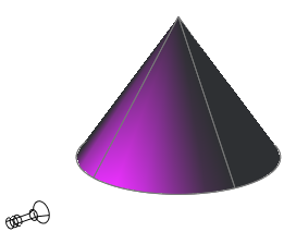
A spotlight distribution casts a focused beam of light like a flashlight, a follow spot in a theater, or a headlight. A spotlight emits a directional cone of light. You can control the direction of the light and the size of the cone. Like a point light, a spot light can be manually set to attenuate its intensity with distance. However, a spotlight’s intensity will also always attenuate based on the angle relative to the spot’s target vector. This attenuation is controlled by the hotspot and falloff angles of the spotlight. Spotlights are useful for highlighting specific features and areas in your model. A free spotlight ( FREESPOT) is similar to spotlight. A spotlight has target properties.
In photometric workflow, the hotspot intensity falls to 50 percent. The hotspot for standard lighting is at 100 percent. At its falloff angle, intensity of the spotlight falls to zero. Additional properties become available for a point light when LIGHTINGUNITS is set to 1 (International SI units) or 2 (American units) for photometric lighting
- Lamp Intensity. Specifies the inherent brightness of the light. Specifies the intensity, flux, or illuminance of the lamp.
- Resulting Intensity. Gives the final brightness of the light. (Product of lamp intensity and intensity factor. Read-only.)
- Lamp Color. Specifies the inherent color of the light in Kelvin temperature or standard.
- Resulting Color. Gives the final color of the light. This is determined by a combination of the lamp color and the filter color. (Product of lamp color and filter color. Read-only.)
Weblights
Photometric weblights provide real-world light distribution. A photometric weblight (web) is a 3D representation of the light intensity distribution of a light source. Photometric weblights can be used to represent anisotropic (non-uniform) light distributions derived from data provided by manufacturers of real-world lights. This gives a far more precise representation of the rendered light than either spot or point lights are capable of.
This directional light distribution information is stored in a photometric data file in the IES format using the IES LM-63-1991 standard file format for photometric data. You can load photometric data files provided by various manufacturers under the Photometric Web panel in the Properties palette for the light. The light icon represents the photometric web you select.
Light that uses a photometric web can be added to a drawing by entering the commands WEBLIGHT and FREEWEB at the command prompt. A weblight targets an object whereas a freeweb light does not.
To describe the directional distribution of the light emitted by a source, AutoCAD approximates the source by a point light placed at its photometric center. With this approximation, the distribution is characterized as a function of the outgoing direction only. The luminous intensity of the source for a predetermined set of horizontal and vertical angles is provided, and the system can compute the luminous intensity along an arbitrary direction by interpolation.
Distant Lights
Distant lights are useful for lighting objects or as a backdrop. A distant light emits uniform parallel light rays in one direction only. You specify a FROM point and a TO point anywhere in the viewport to define the direction of the light. Spotlights and point lights are each represented by a different light glyph. Distant lights are not represented by glyphs in the drawing because they do not have a discrete position and affect the entire scene.
The intensity of a distant light does not diminish over distance; it is as bright at each face it strikes as it is at the source. Distant lights are useful for lighting objects or for lighting a backdrop uniformly.
Sun and Sky Simulation
The sun is a light that simulates the effect of sunlight and can be used to show how the shadows cast by a structure affect the surrounding area. Sun and sky are the primary sources of natural illumination in AutoCAD. Whereas the rays of the sun are parallel and of a yellowish hue, the light cast from the atmosphere comes from all directions and is distinctly bluish in color. When the LIGHTINGUNITS system variable is set to photometric, more sun properties are available.
When the workflow is photometric (the LIGHTINGUNITS system variable is set to 1 or 2) the sun properties have more properties available and are rendered using a more physically accurate sunlight model. The sun color is disabled for the photometric sun; the color is computed automatically based on the time, date, and location specified in the drawing. The color is determined based on the position in the sky. When the workflow is generic or standard lighting (the LIGHTINGUNITS system variable is set to 0), the additional sun and sky properties are unavailable.
The properties of the sun can be modified by using the SUNPROPERTIES command. The Sun Properties window is displayed. The details of the settings are located under SUNPROPERTIES in the Command Reference.
The rays of the sun are parallel and have the same intensity at any distance. Shadows can be on or off. To improve performance, turn off shadows when you don’t need them. All settings for the sun except geographic location are saved per viewport, not per drawing. Geographic location is saved per drawing.
The angle of the light from the sun is controlled by the geographic location you specify for your model and by the date and time of day. These are properties of the sun and can be changed in the Sun Properties window and the Geographic Location dialog box. The time zone used is based on the location, but you can adjust it independently ( TIMEZONE system variable).
Luminaire Objects
A luminaire object is a helper object that assembles a set of objects into a light fixture. A luminaire object groups and manages the components of a light as a whole. Light fixtures can be represented by embedding photometric lights in blocks that also contain geometry. A luminaire object assembles a set of light objects into a light fixture.
Tool palettes of photometric lights are available to provide easy access to create a luminaire object. Luminaire objects are offered through plug-ins. To add a photometric light to be used in a luminaire
- At the command prompt, enter lightingunits and set the value to 1 (International units) or 2 (American units) for photometric lighting.
- Click View tab Palettes panel Tool Palettes.

- Right-click the Tool palette title bar. Click Photometric Lights.
- Drag a light from the palette to the drawing.
- Drag another light from the palette to the drawing.
- At the command prompt, enter block to create a light fixture with the lights placed in the drawing.
