Parallel and Perspective Views
You can create realistic visual effects in a drawing by defining either parallel or perspective projections of a model. The difference between perspective views and parallel projections is that perspective views require a distance between a theoretical camera and target point. Small distances produce severe perspective effects; large distances produce mild effects. The following illustration shows the same model in both a parallel projection and perspective projection. Both are based on the same viewing direction.
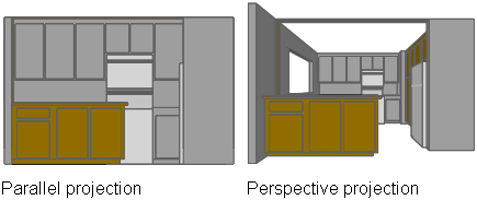
Perspective projections require a distance between a theoretical camera and a target point. Small distances produce severe perspective effects; large distances produce milder effects.
A perspective view remains in effect until the perspective effect is turned off or until a new view is defined in its place.
You can define a parallel projection. To determine the point or angle in model space, you can
- Choose a preset 3D view from the View toolbar.
- Enter a coordinate or angles that represent your viewing location in 3D.
- Change to a view of the XY plane of the current UCS, a saved UCS, or the WCS.
- Change the 3D view dynamically with your pointing device.
- Set front and back clipping planes to limit the objects being displayed.
Viewing in 3D is available only in model space. If you are working in paper space, you cannot use 3D viewing commands such as VPOINT, DVIEW, or PLAN to define paper space views. The view in paper space is always a plan view.
Preset 3D Views
You can select predefined standard orthographic and isometric views by name or description.
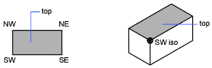
A quick way to set a view is to choose one of the predefined 3D views. You can select predefined standard orthographic and isometric views by name or description. These views represent commonly used options: Top, Bottom, Front, Left, Right, and Back. In addition, you can set views from isometric options: SW (southwest) Isometric, SE (southeast) Isometric, NE (northeast) Isometric, and NW (northwest) Isometric.
To understand how the isometric views work, imagine you are looking down at the top of a box. If you move toward the lower-left corner of the box, you are viewing the box from the SW Isometric View. If you move toward the upper-right corner of the box, you are viewing it from NE Isometric View.
Define a 3D View with Coordinate Values or Angles
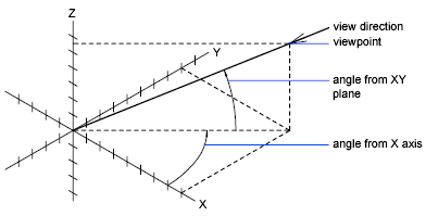
You can define a viewing direction by entering the coordinate values of a point or the measures of two angles of rotation. This point represents your position in 3D space as you view the model while looking toward the origin (0,0,0). Viewpoint coordinate values are relative to the world coordinate system unless you change the WORLDVIEW system variable. The conventions for defining standard views differ between architectural (AEC) and mechanical design. In AEC design, the perpendicular view of the XY plane is the top or plan view; in mechanical design, the perpendicular view of the XY plane is the front view.
You can rotate a view using DDVPOINT. The following illustration shows a view defined by two angles relative to the X axis and the XY plane of the WCS.